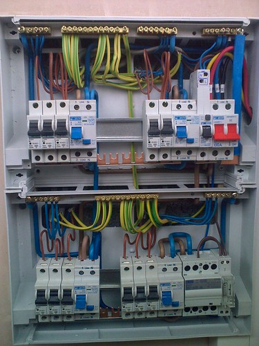
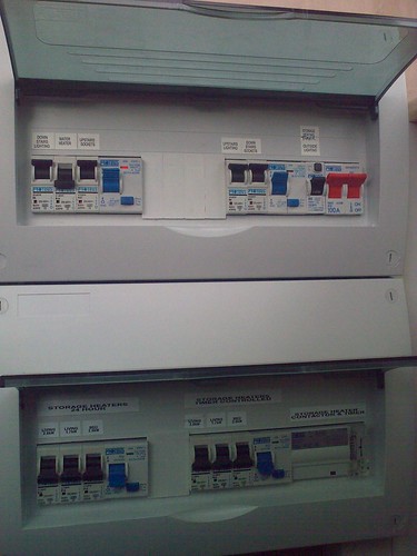
OK, here's another picture (covers on), it may help a little
Right, the reason I did it this way is because I couldn't get an E7 supply over to this board,,, the supply cables were existing 10mm 4core SWA,,, I remember now the supply back at the house was TNC-S and I didn't want to export the earth,, although the SWA armour is earthed at the house I isoated it in trunking beside the CU's (heatshrink IIRC) and stuck a rod in...
Now the std rate supply does go E7 when the teleswitch changes over, and I needed a way to switch the heating (E7) on to charge,,,, they are combi heaters with a fan heater available during the day to top up, that's why there are 2 sets of heater MCBs
")
Back to the wiring specifically..
The timeclock is fed from the RCBO (remember it's a TT now ) and the switched output goes to A1 of the contactor, A2 is connected to the RCBO neutral. The supply comes in to the contactor at the bottom and te switched side (top) supplies the RCD to it's left which in turn feeds the E7 MCB's
I hope that makes sense