Insulation resistance test on live circuit

Talk Electrician Forum

Help Support Talk Electrician Forum:

This site may earn a commission from merchant affiliate links, including eBay, Amazon, and others.

Alessandro

Member
Joined
Mar 5, 2016
Messages
22
Reaction score
0
Location
Acton Town
Obviously the circuit/installation tested should be safely isolated, but...

This is the story: our tutor asked us to find out how insulation resistance can be done on a live circuit. He had to do it once to test several circuits at a military base, and the "client" specifically requested that the whole installation remain live. What the circuits were feeding was a military secret and he was not allowed to leave the room. An armed soldier was guarding the door. That was 15 years ago and he made 500 pounds a day for this job.

I'm only curious, how would you do it? He said that there is ONLY ONE WAY of doing it, but refused to explain how. He said that we should ask around and find the answer.

So the circuits are live and feeding the loads. Even if I only test between lives and earth, there would be continuity through the supply transformer and back through the mass of earth. Any ideas? Or is he just taking the mick?

 
never done it or seen it done, but you could measure IR between lines & earth simply by measuring flow through the earth and a few calculations, although there would be a lot of variables and it would also include anything connected. not just the fixed wiring

 
never done it or seen it done, but you could measure IR between lines & earth simply by measuring flow through the earth and a few calculations, although there would be a lot of variables and it would also include anything connected. not just the fixed wiring


So I could measure current and apply Ohm's law. To get significant values in megohms at, for instance, 400 V I would need an instrument that can measure extremely low values of current. 400 V / 0.0004 A = 1 megohm.

 
I don't think it is possible to establish the insulation resistance of the wiring with a load connected as you will never be able to eliminate the insulation resistance of the load. However you can establish a probable value of the IR to earth of the wiring and the load combined, however it will not be exactly correct.

By measuring the earth leakage with a clamp meter around all live conductors you can then calculate what insulation resistance would allow that leakage current to flow. But the type of load may have a normal earth leakage current which will bias the result. 

 
Bear in mind that if you measure the earth leakage with a suitable clamp meter around all the live conductors (as stated above) Then you will also be seeing capacative leakages to earth (the IR tester does not see these as it uses DC). The capacitance to earth is not an issue and will be a feature of any cable, EMI filters in equipment also add capacitance. In addition if you are measuring leakage to earth on a three phase board, bear in mind that leakages on difference phases to earth will cancel in exactly the same way that neutral currents do.

It is therefore wrong to assume that IR is equal to 230 over the leakage current. Such an approach will most often lead to a pessimistic value being assumed for IR.... though in some cases, it might go the other way.

That said. An earth leakage clamp is good for getting a rough idea when you cannot isolate the board. If you clamp on and find 1A going missing (An extreme case, but I have seen it*) then you can pretty much assume that IR is bad, you could then then go through the circuits and clamp individually to find which one(s) it is likely to be. I have done something similar prior to a global IR, I had a limited window to shut down the board so I went in knowing that "global is likely to be bad, but its likely circuit 5L3 pulling it down, so we will then remove that circuit and re-try the global IR" It was spot on, global was fine with that circuit disconnected and I've saved time over going over them in turn

Conversely if you clamp a fully loaded 12 way TPN board and there is 10ma missing, you would probably guess the there isn't likely to be a great deal wrong with it. Even though that value only equates to 23K if you tried to apply ohms law.

As a go/no go check, it has its beneifiets where you can't do IR, but it is a poor subsitute

*Normally down to black/grey confusion on harmonised 3C SWA used for single phase, due to the ends being made of by different guys who use the cores differently..... Never had this problem with the R/Y/B!

 
*Normally down to black/grey confusion on harmonised 3C SWA used for single phase, due to the ends being made of by different guys who use the cores differently..... Never had this problem with the R/Y/B!
Because sensibly, Blue was used for neutral in a single phase install and everybody knew a blue cable in single phase was N.

But now we are "encouraged" NOT to use the black as N as that would "confuse" people (WHY?) so we are encouraged to use the grey instead as N.

 
Last edited by a moderator:
Because sensibly, Blue was used for neutral in a single phase install and everybody knew a blue cable in single phase was N.

But now we are "encouraged" NOT to use the black as N as that would "confuse" people (WHY?) so we are encouraged to use the grey instead as N.
I heard it was to stop,people associating the black with neutral......WTGrape

we have to associate the black with being a neutral when it is on any older cable

wazzocks!

 
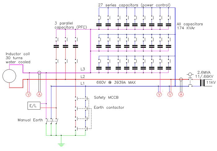
There is a way to do live IR tests by using DC injection through high impedance chokes. We used it for monitoring the induction furnaces.

I’ve got the power drawing for one of the furnaces, all it shows is a mysterious box with the connections to it.

Power.jpg


Last edited by a moderator:
This wouldn't be an earth-free (IT) supply would it? They are used in operating theatres and in some military/broadcast applications. Worth asking your tutor for clarification. 

 
....................In addition if you are measuring leakage to earth on a three phase board, bear in mind that leakages on difference phases to earth will cancel in exactly the same way that neutral currents do..........
Maybe I'm misunderstanding. If you clamp all 3 phases of any 3-phase circuit simultaneously or 3 phases and neutral if there is one then you should see the cumulative leakage current of all the phases.

 
Last edited by a moderator:
Top