Electromagnetic Brake

Talk Electrician Forum

Help Support Talk Electrician Forum:

This site may earn a commission from merchant affiliate links, including eBay, Amazon, and others.
Joined
Mar 12, 2011
Messages
3,608
Reaction score
181
Location
Psychiatric ward??
Hi All!!

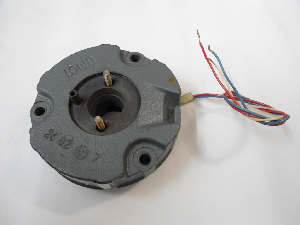
Now, my lathe i am doing up has an electromagnetic brake on the motor spindle. Have a look at the photo and tell me what you think?? Problem is, is it worn out???? See, i would have thought that the friction material would stand proud of the housing, but perhaps it is meant to be flush???

What you think?? assuming it is worn out, what sort of mega money do these things cost??

I can post a part number if needed, but it is about 5" diameter, so not a huge thing..

Brake.jpg


What you all reckon?? be nice to have it working....

john...

 
is that not just the magnet part of the brake,the brake disk and springs are not shown, as far as I can see,did the shaft has no parts attached?

 
Hi Paul, Yes!! i will post the details off it tomorrow!!

Hi poni,

That is the way it is!! when you operate the thing it pulls a flat brake disc [mounted on the motor pulley towards it. I will post more pictures tomorrow!

john..

 
So it's a power to brake unit rather than a power off to brake unit?

BTW, been looking at testing welders today in compliance with BSEN60974-1/-4/-9.

Looking @ around £100 in bits to build the test kit for the OCV, & the primary & secondary leakage to comply with the standard test procedures, & one of those bits is from ebay!!!

Build time about 3 hours, plus the research & design time today.

 
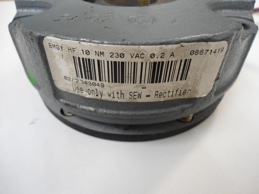
Being the hoarder I am I "collect" various bits rather than bin. Got some salvaged brake assemblies off of 3-ph SEW motors if any good? 230VAC, 0.2A, 3-wire.......don't know if you could adapt? Gratis if you want. Lenze ones too somewhere.

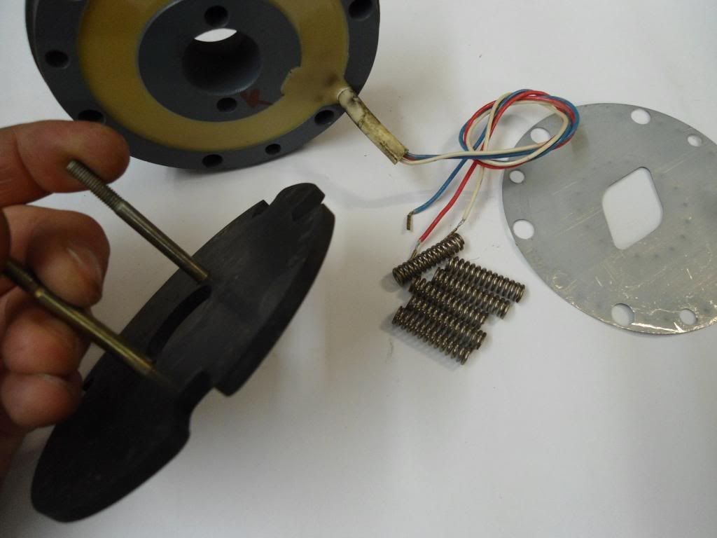
Used with a rectifier (have those too) then power gets applied and initialises the acceleration coil on the red and white. After about 120ms the white gets switched out and blue gets switched on i.e the full coil. Disc btw is 110mm so about 4 5/16" in old money.


Basically all the "guts" shown here:

http://bever.bg/BG/Drive%20Academy/Brake%20Service%20and%20Maintenance.pdf

 
Last edited by a moderator:
so its not a brake unit its a  electromagnetic clutch at bit like this

Lenze-Electromagnetic-Clutches-Brakes.jpg
if the friction material has worn way you will need to replace it

 
I'm not sure from the photo in the OP if it's a brake or whether it engages the pulley with the drive belt in which case it's an electrically operated clutch.. Can you post a photo of the components that were mounted on the shaft?

 
I did some work on a table saw at work and that had a dc module that just injects DC into the 3ph motor windings and brings it to a complete stop then switches off. No brake module as such on the motor as far as I know ie dynamic braking as used with inverters on hoists although a mechanical brake has to take over on a hoist.

 
Last edited by a moderator:
I did some work on a table saw at work and that had a dc module that just injects DC into the 3ph motor windings and brings it to a complete stop then switches off. No brake module as such on the motor as far as I know ie dynamic braking as used with inverters on hoists although a mechanical brake has to take over on a hoist.
Pretty sure we use to that DC plugging, but I could be wrong as my memory is shot.

 
Hi all,

Yes! it is just like the photo Poni has posted!!! I got it working yesterday so it seems fine. The only thing i cannot understand, is that the friction material is flush with the steel housing. I would say that this makes it worn out!! HOWEVER, in all the photos i have seen of them the friction material IS flush with the housing...

Furthermore, i found that they are now made by Lenze [was Simplatrol] Anyway, I found a drawing. On there, it shows the thing as being 24mm thick, well, apart from 0.1mm mine is!!! so is that ok????

Poni, how come you know about them?? do you work on them, as mine is EXACTLY like the one you show. Is the friction material meant to be flush with the housing??? I will go and take some photos!!

Thanks all

john...

 
Hmmm, Just spend an hour and a half composing a post with all photos, only for a message to appear telling me i was trying to post too many photos.....

Not sure how to get round that...

john...

[SIZE=medium]Hi all!![/SIZE]

[SIZE=medium]Here we have a picture of the bit that mounts on the motor shaft. As you can see, fitted to the end are some weights with friction material on them!![/SIZE]

[SIZE=medium]
1.jpg
[/SIZE]

[SIZE=medium]Here are the weights with the friction material..[/SIZE]

[SIZE=medium]
2.jpg
[/SIZE]

[SIZE=medium]They fit together like this...[/SIZE]

[SIZE=medium]
3.jpg
[/SIZE]

[SIZE=medium]Over the top of them there is like a "brake drum" type thingy!!! You will be able to see that the "weights" should be driven by pins but i have removed tham as they were worn and i was going to replace them[/SIZE]

[SIZE=medium]See here....[/SIZE]

[SIZE=medium]
4.jpg
[/SIZE]

[SIZE=medium]It all goes together like in the photo below. You will see that as the shaft spins up, it will drive the "Brake drum" thingy[/SIZE]

[SIZE=medium]
5.jpg
[/SIZE]

[SIZE=medium]Attached to the "brake drum" is a pulley. This pulley then drives the lathe. Idea of all this, is to act as a "mechanical" soft start if you like.[/SIZE]

[SIZE=medium]See here...[/SIZE]

[SIZE=medium]
6.jpg
[/SIZE]

 
Wonder if it will let me post anymore photos???

[SIZE=medium]Attached to the "brake drum" is a pulley. This pulley then drives the lathe. Idea of all this, is to act as a "mechanical" soft start if you like.[/SIZE]

[SIZE=medium]See here...[/SIZE]

[SIZE=medium]
6.jpg
[/SIZE]

[SIZE=medium]Here is the complete assembly from another view![/SIZE]

[SIZE=medium]
7.jpg
[/SIZE]

[SIZE=medium]Now, Here is the brake i have been on about...[/SIZE]

[SIZE=medium]
8.jpg
[/SIZE]

[SIZE=medium]The Armature bolts to the pulley as shown here....[/SIZE]

[SIZE=12pt]
9.jpg
[/SIZE]

[SIZE=medium]And the brake stator is fitted next to it as shown below, The bit bolted to the pulley is on a flexible backing plate held on by the rivets you can see. When the brake is switched on, [When you hit the emergency stop on the lathe] the motor is switched off and the brake is switched on and stops the thing very quickly!![/SIZE]

10.jpg


[SIZE=12pt]
11.jpg
[/SIZE]

Couple more photos!!

[SIZE=medium]Problem is, how do you know if the brake is worn?? The friction material is flush with the steel housing, as i will show in the next few photos. I cannot see that this is right, but all the photos i have looked at on the internet all look like mine!!! Further, as i said, the entire thing is supposed to be 24mm thick. Apart from 0.1mm [4 thou] mine is!!!![/SIZE]

[SIZE=medium]
12.jpg
[/SIZE]

[SIZE=medium]
13.jpg
[/SIZE]

[SIZE=medium]
14.jpg
[/SIZE]

See what i mean??


Here again is the brake fitted to the motor..


Now, the clutch assembly is badly worn, so what i am going to do, is to dump it and fit a modern soft start. I would like to keep the brake though, so i am going to make a new centre for the "old" pulley and brake disc and refit them to the lathe. I will modify the old clutch centre shaft that fits the motor spindle, and use one of the flanges on it to fit a "flywheel" as i would like to retain the "flywheel effect" that the thing had originally, owing to the weight of the old clutch. [Must all weigh about 25 pounds if not more!!!] Obviously i will do this on my other lathe cos this one is in bits!!!
What you all reckon????
john...
 
I now see, the first part you have shown is a centrifugal clutch and the last part is the fixed brake the weights are thrown out under centrifugal force from the spinning shaft of the motor.

when the motor is turned off the spinning stops and the weights drop back then the brake catches the brake disk and stops the work  

as for the friction material, without the maintenance manual its hard to tell if it should be proud of the brake or not ,but looking at the clutch there was very little wear to it so the brake may be meant to be like that(like Canoeboy said it looks like resin), does it work OK?

Should it be on the E-stop circuit (should it no fail safe on loss of supply) or did you mean the duty stop?  

 
Last edited by a moderator:
I did some work on a table saw at work and that had a dc module that just injects DC into the 3ph motor windings and brings it to a complete stop then switches off. No brake module as such on the motor as far as I know ie dynamic braking as used with inverters on hoists although a mechanical brake has to take over on a hoist.
Quick and dirty way of stopping a squirrel cage motor, turns a pair of windings into a bar magnet and grabs the rotor to a stop, plus it was on all the HSE guidance when PUWER98 begun to require stopping of tooling on wood machines in start time, 10s, or max of 35 sec depending on machine.

Some sense back from the motor to see if it is still turning, the cheaper ones are just set up on current/voltage/time to stop the motor as required.

Pretty sure we use to that DC plugging, but I could be wrong as my memory is shot.

Plugging was generally taken as reversing the motor direction, this could be "on" all the time until stop, or could be pulsed, depending on the control.

 
Hi Paul,

A thing called a Vöest-Alpine DA180. Is a big solid thing!! Wants a coat of paint and a bit of a sort out, but it is basically a good one i think!! metric imperial screwcutting and module and diametral pitch pitches too. Very heavily built thing!! Just my little project!! They make mega bucks back in germany. I wonder how it got here... All the labels are in german you see, so i think it must have come off a ship or something, as no-one is going to sell lathes here with german safety instructions!! Did not cost me a lot, so i think i will do ok with it!! Should make a nice partner to the Harrison..

john...

Hi Canoe, Yes, i think that is the friction material, unless the friction material is the metal to metal bit. I have looked at loads of photos of them, and they are all flush like mine. Here is a bit of a catalogue with lenze brakes in it. See the photo on the first page?? See, it looks just like mine... http://www.icpltd.co.uk/icp_pdf/lenze/Clutches%20&%20brakes/Lenze%20Eletromagnetic%20Clutches%20&%20brakes.pdf

john..

 
Top