- Joined
- Dec 25, 2011
- Messages
- 5,468
- Reaction score
- 78
A few questions here relating to a practical application I have. I've designed my own electric sliding gate system for the front of the house as in done the CAD and had the frame made then designed the posts, guide rollers etc and made them myself. The gate frame is all made, the gate posts are in and the drive kit bought from Easygates. Now, the "norm" is to place the control PCB in the same enclosure that houses the motor that drives the gate. I don't want to do this so will be siting the control pcb in it's own enclosure in the garage. In terms of cable length the from the enclosure to the gate motor it's approximately 14m.

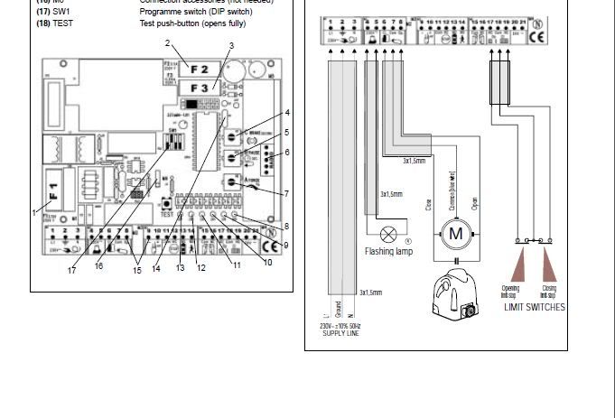
The basic wiring diagram is shown below:

I'm planning a 2' ish deep trench dug from the garage to the post with the cabling laid therin with all the proper cable tapes etc a la the OSG. Here's where I'm unsure. In the trench will be an SWA feeding the gate motor with 230V. Also a separate SWA for the various pillar lights (lights on their own breaker). Then, in the same trench, I have the 24v line to the flashing lamp, limit switch lines, photocell wires (not shown)and keypad 10-core cable (not shown). I will also include intercom line and quite likely CCTV cabling.
If I'm reading the OSG correctly then the SWA, by virtue of the earthed armour offers protection against "harmful mutual effects" so I don't need to worry about maintaining a 50mm separation. The text that comes with the gate kit says:
"Do not use any fixed copper lines. Do not lay any 230 volt cables in parallel and do not lay any 2 cables in the same cable trunking".
Are they meaning between the individual 24V lines? Am I worrying too much? Should I just whack it all? I was considering running the armoureds on their own then all the control cabling in say a 50mm corrugated plastic cable duct.
Any thoughts/suggestions appreciated.
Cheers

The basic wiring diagram is shown below:

I'm planning a 2' ish deep trench dug from the garage to the post with the cabling laid therin with all the proper cable tapes etc a la the OSG. Here's where I'm unsure. In the trench will be an SWA feeding the gate motor with 230V. Also a separate SWA for the various pillar lights (lights on their own breaker). Then, in the same trench, I have the 24v line to the flashing lamp, limit switch lines, photocell wires (not shown)and keypad 10-core cable (not shown). I will also include intercom line and quite likely CCTV cabling.
If I'm reading the OSG correctly then the SWA, by virtue of the earthed armour offers protection against "harmful mutual effects" so I don't need to worry about maintaining a 50mm separation. The text that comes with the gate kit says:
"Do not use any fixed copper lines. Do not lay any 230 volt cables in parallel and do not lay any 2 cables in the same cable trunking".
Are they meaning between the individual 24V lines? Am I worrying too much? Should I just whack it all? I was considering running the armoureds on their own then all the control cabling in say a 50mm corrugated plastic cable duct.
Any thoughts/suggestions appreciated.
Cheers


