Advice Needed On Test Results

Talk Electrician Forum

Help Support Talk Electrician Forum:

This site may earn a commission from merchant affiliate links, including eBay, Amazon, and others.

redman

Member
Joined
Mar 7, 2009
Messages
85
Reaction score
0
Location
Nottingham
Hi all,

Ive just done an electrical inspection & test on my own house.

Ive not had any problems with the electrics over the past 3 years that i`ve lived here.

I`ve done it, mainly to get some testing practice, also just to see if it complies with the current regs.

The consumer unit has a sticker saying it was changed in 2004 & has RCD protection on everything apart from the lights.

Most of the test results are good, its just 2 circuits that are a bit dodgy.

1st circuit -

 Lighting - 1.0mm t&e - B6 MCB

         R1+R2 = 1.53 ohms

Ins Res: L/N =  >200  M ohms

              L/E =  > 200 M ohms

              N/E =      25 M ohms

                Zs = 1.68 ohms

Although these results are within the figures from the on site guide, I still think there is an issue with the neutral / earth insulation resistance test. But because this circuit is not on an RCD, nothing has ever tripped.

Then the 2nd circuit -

kitchen Ring - 2.5mm t&e - B32 MCB

         r 1 = 0.17

         r 2 = open circuit

         r n = 0.18

R1 + R2 = 0.26

Ins Res:  L/N = >200 M ohms

               L/E =       8  M ohms

               N/E = > 200 M ohms

                 Zs = 0.36 ohms

RCD: X1 = 98ms

          X5 = 23ms

I think this just appears to have a break in the CPC somewhere on the ring. 

Ive checked all the socket connections & they look ok. 

The cables are under floorboards or on the wall, burried in plaster. So ive not been able to visualy check the cable route. 

So..... what would you guys do now in this situation, regarding these 2 circuits ?

Any advice welcome,

Cheers

 
Okay, where to start?

First circuit, IR N-E 25M ohm would not trip an RCD even if one was present.

High R1+R2 start looking for a dodgy light switch on the light fitting you tested at.

Second circuit:

R2 open circuit,  start splitting the ring at each socket and test to identify which leg of the ring has the open circuit CPC. then investigate and fix / replace that leg.

 
Last edited by a moderator:
1 split the ring at the approximate middle,

2 disconnect the ring from the CU

3 then do a long lead to your middle point from ONE side of your disconnected CPCs

4 that will give you what 'side' the fault is on,

5 then split that side again,

6 repeat 3

7 repeat 5

8 repeat 6&7  etc etc etc

thats not how I do it,

but that is the text book format

 
As Dave says,,

It'll either be a dodgy switch or loose termination for the lighting circuit

For the ring final I'd disconnect both ends of the ring at the CU and then connect the L&N of one end together... if you then continuity test at each socket between L&N the readings should gradually rise as you go along the ring. Eventually you'll find that it'll go open circuit. Once you've tested at each socket and noted the readings you'll have an idea of how its been wired.. you should find the open circuit earth between the highest reading socket and one of the ones that gave you an open circuit reading.

 
Once you had an "open r2" on the ring - at that point you stop testing the ring - as every other concurrent test is worthless!

The lighting circuit may, or may not have an issue - depending how large a circuit it is - but the ring is another matter.

I`d fault find it the way Albert suggested (actually, I`d probably do it a different way, but not one I`m going to advocate here!)

 
Hi all,

Ive just done an electrical inspection & test on my own house.

Ive not had any problems with the electrics over the past 3 years that i`ve lived here.

I`ve done it, mainly to get some testing practice, also just to see if it complies with the current regs.

The consumer unit has a sticker saying it was changed in 2004 & has RCD protection on everything apart from the lights.

Most of the test results are good, its just 2 circuits that are a bit dodgy.

1st circuit -

 Lighting - 1.0mm t&e - B6 MCB

         R1+R2 = 1.53 ohms

Ins Res: L/N =  >200  M ohms

              L/E =  > 200 M ohms

              N/E =      25 M ohms

                Zs = 1.68 ohms

Although these results are within the figures from the on site guide, I still think there is an issue with the neutral / earth insulation resistance test. But because this circuit is not on an RCD, nothing has ever tripped.

Then the 2nd circuit -

kitchen Ring - 2.5mm t&e - B32 MCB

         r 1 = 0.17

         r 2 = open circuit

         r n = 0.18

R1 + R2 = 0.26

Ins Res:  L/N = >200 M ohms

               L/E =       8  M ohms

               N/E = > 200 M ohms

                 Zs = 0.36 ohms

RCD: X1 = 98ms

          X5 = 23ms

I think this just appears to have a break in the CPC somewhere on the ring. 

Ive checked all the socket connections & they look ok. 

The cables are under floorboards or on the wall, burried in plaster. So ive not been able to visualy check the cable route. 

So..... what would you guys do now in this situation, regarding these 2 circuits ?

Any advice welcome,

Cheers


Just a few comments re your circuit #1 lights and your statement about RCD's and tripping...

you need to stop and think about some regs....

Table 61 page 191 of BS7671 tells us 1.0Meg is acceptable...

So if the regs say 1.0Meg is acceptable...

1.0Meg is NOT going to trip any RCDs either!!!!!!!

And you need to stop and think about the Maths.....

30ma trip current or greater @ 230v would only be drawn through a resistance of ..

230v/0.03A = 7666.67ohms  or call it  7.7kohms or less...

So 1Meg or your 25Meg are well clear of any RCD issues.. (If one was fitted)

BUT..

you are right being concerned when one pair of legs of a circuit is much lower than the other legs....

normally the insulation around a cables conductors would all deteriorated at a similar rate..

So you need to decide...

Is it damaged cable.....

Damaged joint...

Damaged accessory connected somwhere...

think where damp, insects, may have got into a fitting or j/box.. or water into an external fitting PIR etc...

Or any recent building work that could have damaged a cable ??

As you say...

not a major concern as it is over 25Meg..

But I would probably do a bit of extra investigation to see if I could narrow it down a bit more...

p.s.

good post & question...

& great sticking some actual results down..

makes it easier to have a bit of meat to get your head around to dicsuss..

nice one!!

Guinness

 
Last edited by a moderator:
Thanks for your help guys.

So............ i`ve managed to locate which part of the ring has the break in the CPC.

The good news is, I can see the cable from underneath in the cellar. (this looks ok)

The bad news is, the cable goes up the wall to a socket above the work top. Which is burried in plaster & tiled.

The other end is a low level socket that supplys the fridge.

Now I just need to figure out how to replace this leg, without trashing the kitchen. headbang   

 
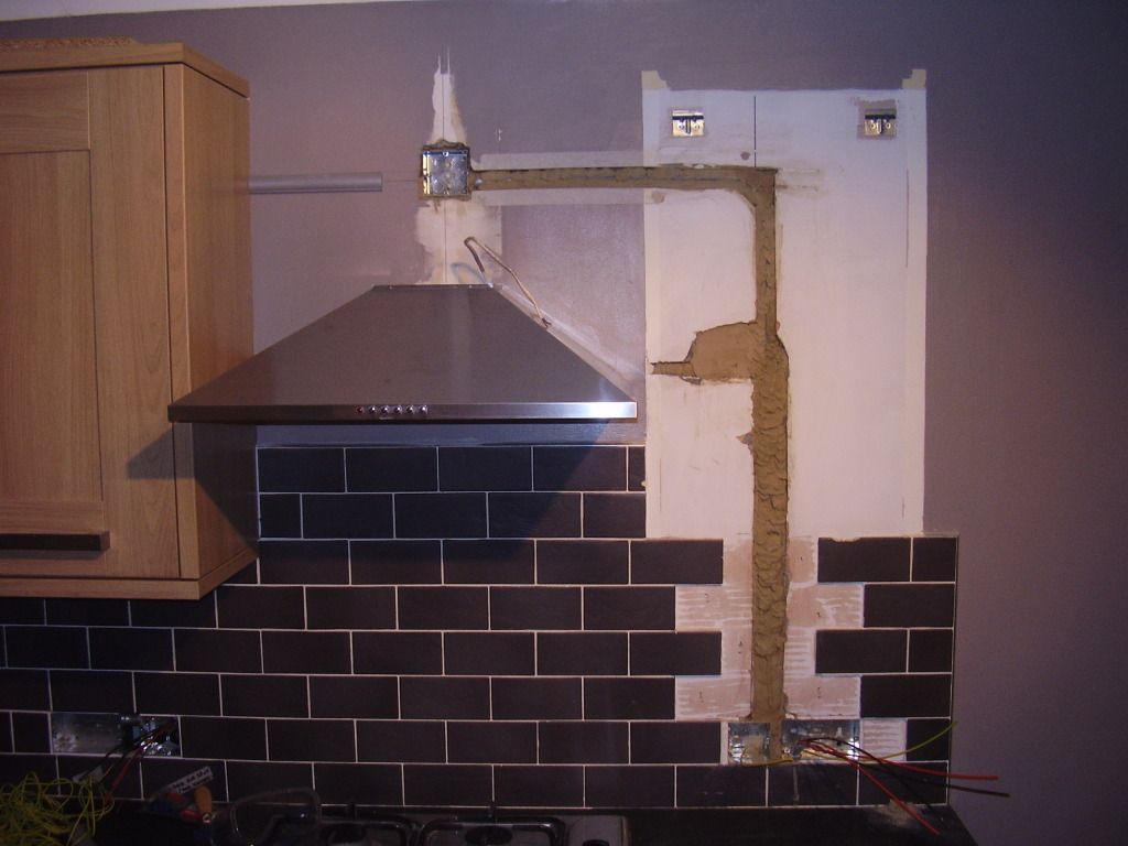
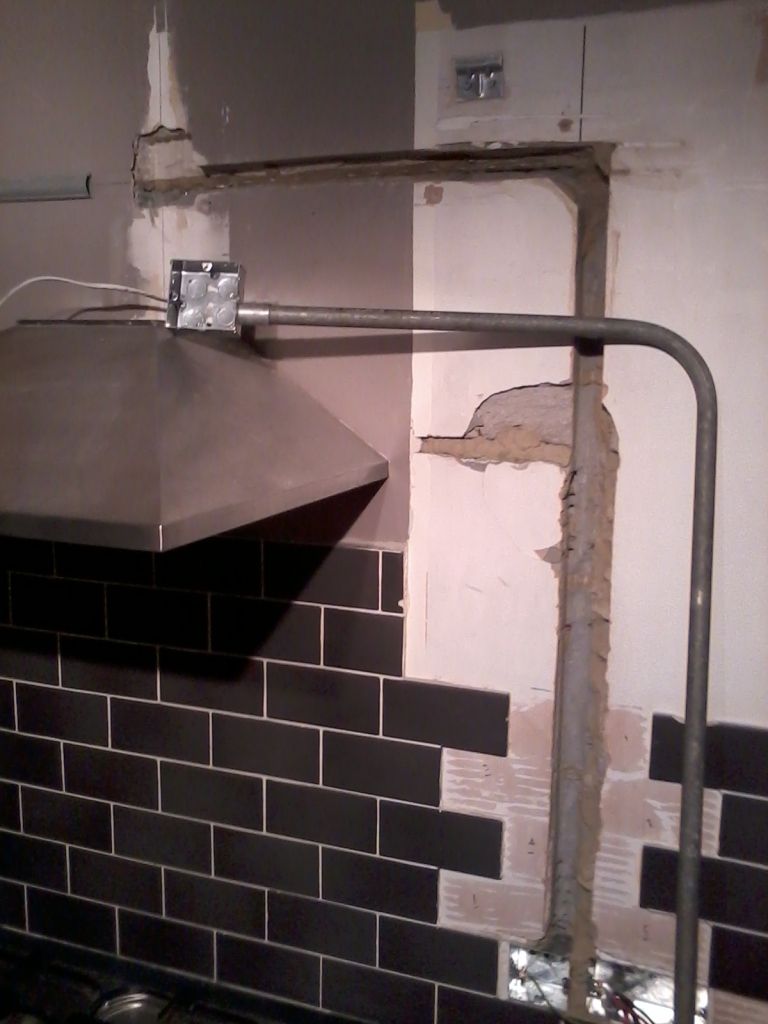
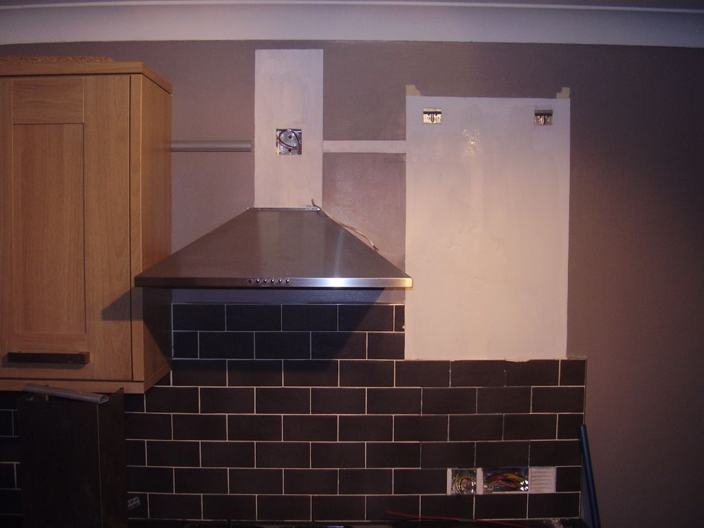
Tiles? No problem (maybe  :lol: )..............get yourself a multi tool. Use it to cut through the grout. Use it then to chisel off the old grout o you can re-use the tiles. Even use it to chase out the walls if Celcon. One of the best bits of kit I've ever bought!

Tiles off:


Bit of conduit etc:


Tiles back on:


Last edited by a moderator:
Redman, for the long leg, unterminate the cables in the socket first, then:

ID the cable that is defective

Snip back the L & N right down to the outer sheath - do NOT snip the CPC.

Strip back the new cable in the same manner.

Bend each of the CPC's to 90 degrees of the twin and earth.

Join the 2 cables by twisting each CPC together - make sure that the twist is tight.

Fold back the CPC's again the direction of travel.

Tape the CPCs to the new cables tight - start at the point of twist and move back.

Pull gently.

Andy Guinness

I was thinking of trying something like this.

Not sure if the cable is clipped, or in capping under the plaster, but its gotta be worth a try. :pray

The annoying thing is, this looks like the newest circuit in the house. I reckon it was put in with the kitchen about 5 years ago.

Probably wasnt tested at the time.

TBH though it would be quite unusual for there to be a break in a cable,,,,, its more likely got a join in it
Looking at the cable from the cellar, it all looks ok.

So.... I guess it may have been hit when the skirting board or cupboard bases were fixed to the wall.

 
Take the skirting off and check for a nail through the cable.

If so the upper part in the plaster can remain, and join on a new section down to the cellar with an appropriate junction.

 
Top