- Joined
- Dec 25, 2011
- Messages
- 5,456
- Reaction score
- 69
Just helped a mate out with his sliding front gates. Overkill for an ex council place if you ask me but he's got no kids and is easily bored! Sad thing is I've DONATED bits from my own as yet unfinished more complex gate project. Still a good mate so it's what you do. He's a chippy by trade. I "advise" on the mechanical & electrical element and he takes most of that on board though he tends to do things and ask me afterwards which often leaves me shaking my head. It goes: "It's not the right way to do it John!" and he says "Yeah! But it'll be alright won't it?".
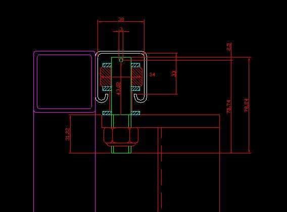
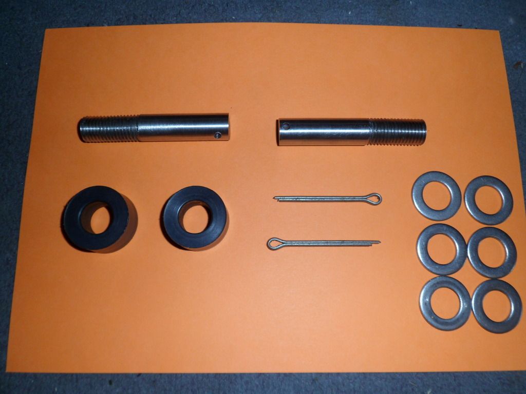
I came up with the idea of using Unistrut as the guide rail and the idea for the motor controls housing based on that hotel in Dubai. I made up the shafts and rollers in stainless & nylatron and supplied the materials for the housing along with various electrical bits and the Unistrut. John used a recycled steel frame he got from work, cut n shut it then added the slats. I left all the builder's work to him. Much coffee and biscuits were gotten through doing this with many fag packet sketches:
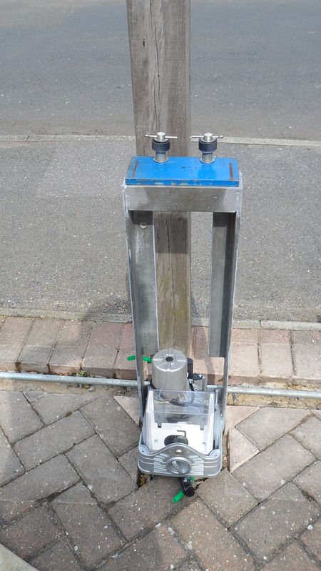
Rollers:
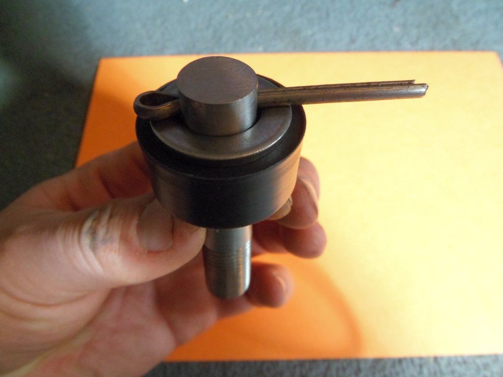
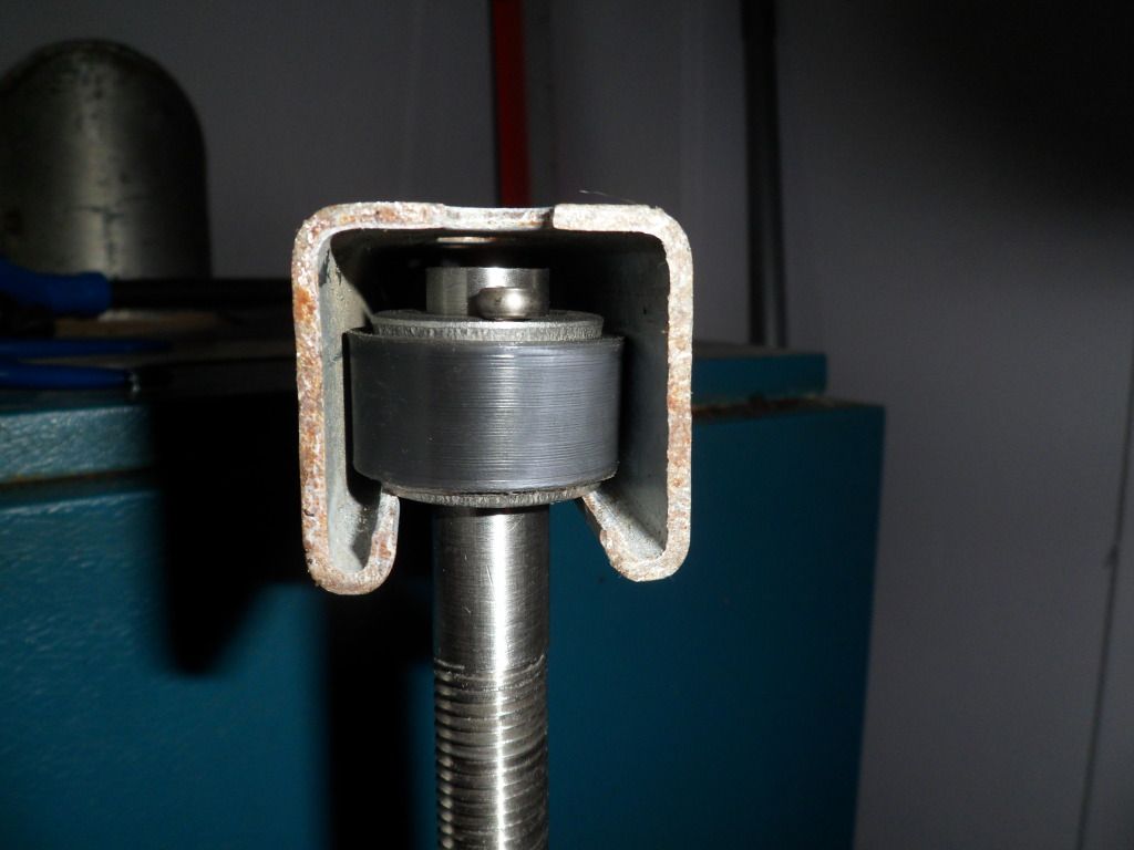
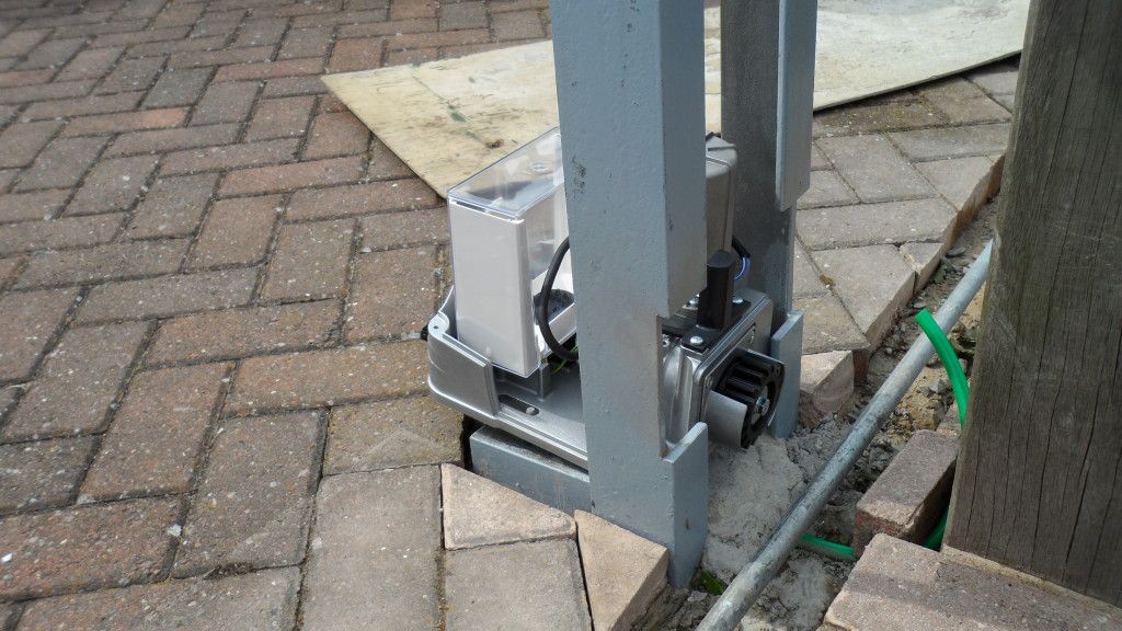
Mechanics:
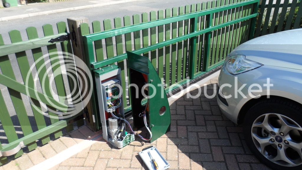
Electrics:
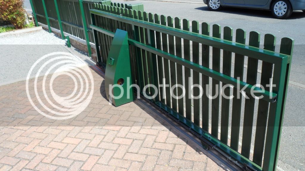
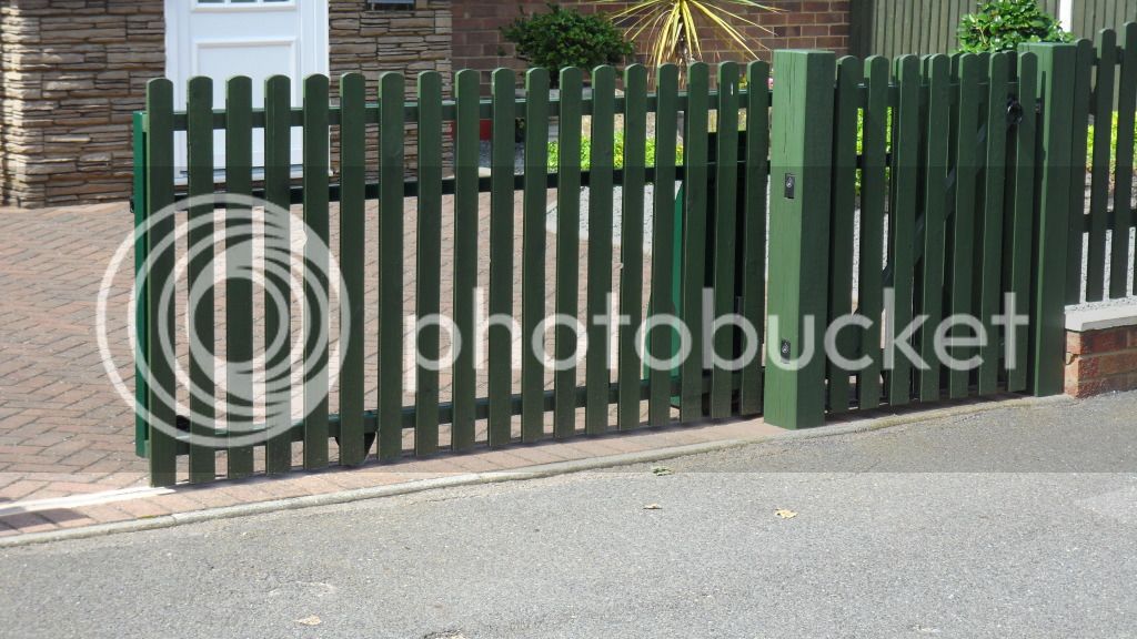
Finished article:
Added a 24VDC break beam so the side gate cuts the sliding gate operation. He wouldn't have the strobe at all to start with so I came up with the idea of placing it INSIDE the enclosure with perspex windows. TBH only really visible at night. Added a genuine FORD switch to one of the blanks on his Focus dash and mounted the transmitter under the dash. It does work very well and look the part IMO. Going to add safety edges shortly.
I came up with the idea of using Unistrut as the guide rail and the idea for the motor controls housing based on that hotel in Dubai. I made up the shafts and rollers in stainless & nylatron and supplied the materials for the housing along with various electrical bits and the Unistrut. John used a recycled steel frame he got from work, cut n shut it then added the slats. I left all the builder's work to him. Much coffee and biscuits were gotten through doing this with many fag packet sketches:
Rollers:
Mechanics:
Electrics:
Finished article:
Added a 24VDC break beam so the side gate cuts the sliding gate operation. He wouldn't have the strobe at all to start with so I came up with the idea of placing it INSIDE the enclosure with perspex windows. TBH only really visible at night. Added a genuine FORD switch to one of the blanks on his Focus dash and mounted the transmitter under the dash. It does work very well and look the part IMO. Going to add safety edges shortly.
")