Three Phase roller shutter door wiring

Talk Electrician Forum

Help Support Talk Electrician Forum:

This site may earn a commission from merchant affiliate links, including eBay, Amazon, and others.

Rocketman

Junior Member
Joined
Sep 16, 2012
Messages
2
Reaction score
0
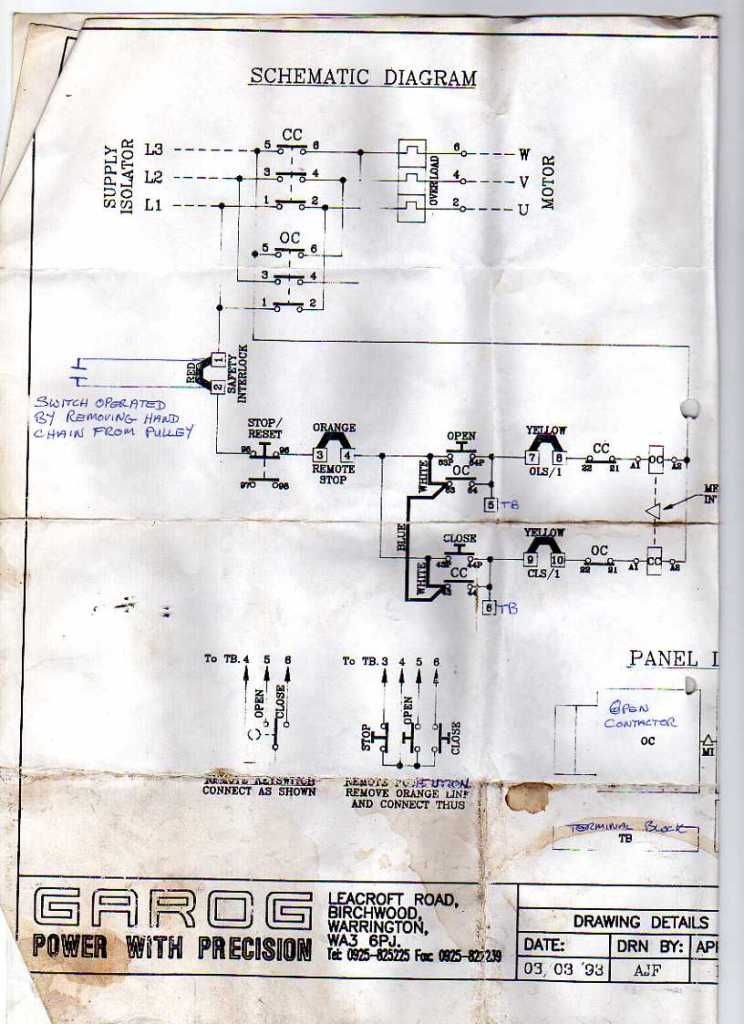
I am looking for some help and guidance on how to wire a three phase roller shutter door motor and control box.

We have a Garog three phase motor with in built limit micro switches see fig 1 and fig 2.

The control box has up down and stop for controlling the door see fig 3 and 4,

I really need a wiring diagram to make some sense and get this door electrified.

The motor was already fitted in the workshop but all the electrics and control gear had been removed, we purchased the control box second hand but obviously there was no diagram.

Any help would be greatly appreciated.

Fig4.jpg

Fig1.jpg

Fig2.jpg

Fig3.jpg

 
K1 will be UP contactor,

K2 will be DOWN contactor,

From UP button you need to find which wire operates the coil control of K1,

And likewise with K2 from the DOWN button once you've sorted that it will be straightforward to finish it off,

Stop button will be common to both K1and K2

Shouldn't take more than 30 mins to an hour to sort out.

 
img376_zps251ae3d5.jpg


Have a bash at this Elton.

 
You're gonna get told off! :)
O) There was no telling off, if any plans are posted on open forum they must not have copy right, and if they do, the correct permissions should be given.

In the above post I can not see any copy right information therfore I can not moderate, I can only assume that the plan is indeed not copy right and allow it to be reproduced here. If it is under copy right than the poster and not the forum is responsible.

 
O) There was no telling off, if any plans are posted on open forum they must not have copy right, and if they do, the correct permissions should be given.In the above post I can not see any copy right information therfore I can not moderate, I can only assume that the plan is indeed not copy right and allow it to be reproduced here. If it is under copy right than the poster and not the forum is responsible.
Fair enough, I get what you mean. Try this with Window's 7 Snipping tool:

Guthrie Douglas / Garog Keyswitch Relay Unit - Roller Shutter Motor etc | eBay

 
I checked the other side of the diagram and there is no mention of copyright ...phwew !! could have been arrested there by the Electric Police .

The coffee stain , however, was designed with great precision and therefore is copyright to Evans Electric and should not be reproduced on any public media without the prior permission of the owners.

Please contact :-

Brian

C/o Evans Electric

The Shire

Middle Earth

North Birmingham.

 
thanks to Evans Electric for the diagram that will be a great help

Regards Rocketman

 
lets be honest about it, companies want their kit fitted and working well, no company (sensible) would object to posting a simply wiring diagram. Now if you posted the circuit diagram for the internal control circuit / PCBs that might be a diferent issue...

 
lets be honest about it, companies want their kit fitted and working well, no company (sensible) would object to posting a simply wiring diagram. Now if you posted the circuit diagram for the internal control circuit / PCBs that might be a diferent issue...
I agree, the risk is very low however ,I would rather the forum not take the risk any action being taken against it.

 
Hi to all you contributors. I am in the same situation as Rocketman was. My remit is to get the second hand, three phase, Garog door gear wired, tested & operational. I was presented with the gear installed for a roller shutter door in a tractor shed. There was an energised TPN (no earth provision), 1.5mm2 4core SWA connected to a Crabtree C50 4 X 30A board in another  shed. The idiot handyman had utilised a handy spare grommet to enter the DB & had simply trimmed the armouring with no glanding for earth continuity! He had used a spare TP 30A MCCB to supply this sub-circuit!

Approximately 35metres down stream in the tractor shed was a 4pole switch disconnecter, energised, ready for me to use.

The client & his handyman were there as I assessed the job. They were dissappointed that I didn't start, there & then!

I explained in no uncertain terms the lethality of their dabbling, & promptly de-energised & disconnected the supply.

I have returned to gland the cable, into a metal enclosure for the 100A switch disconnector & a stand alone 63A 30mA RCD. The system is TNS so I will be utilising the armouring for earth continuity. There are no external services, introducing extraneous, conductive, surfaces, so I have not run 10mm2 6491X GY for earth bonding. I haven't calculated the volt drop as yet, the client would be really miffed if I said that  1.5mm2 was inadequate, don't you think? I have run 20mm HIP conduit from the starter,up/down/stop switches, these I mounted the opposite side to the door gear motor 8metres away.

I am posting this as any input is appreciated, I am 62years of age, (never too old to learn). I served my apprenticeship, 1966-1971, and an Approved Contractor/Domestic Installer registered with NICEIC. If any of you sparks out there want help with Television Broadcasting wiring problems, I am a qualified Electronics Wireman, (hence the title). I am a registered Bang & Olufsen Installer so for MasterLink or PowerLink wiring problems please feel free to ask.

 
Welcome to the forum, Wireman.

I am a bit confused about the over current protection for the circuit.

What is the motor rating on the door gear as a start?

 
Hi.

You`ll be aware of the older B&O kit too, then, I suppose?

I`ve diagrams & spares here for B&O ( and Quad) kit ( including matched thermionic valves) - if you, or anyone you know, is interested.

A certain family member was a top UK B&O service engineer for many years :) :)


Latest posts

Top