Contactor Help

Talk Electrician Forum

Help Support Talk Electrician Forum:

This site may earn a commission from merchant affiliate links, including eBay, Amazon, and others.

mk1rob

Junior Member
Joined
Mar 12, 2012
Messages
37
Reaction score
0
Hi guys

Ive just done a EICR at a doctors surgery. Theres a single phase rewireable fuse board for the main circuits (lights, rings etc) and a separate 3 phase board for the electric convector heater radials. This 3Ph board is supplied from another enclosure with a contactor in it (see pic)
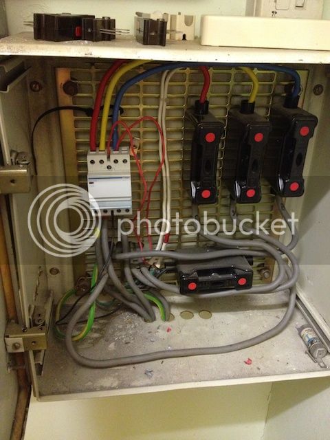


Ive not had a lot of experience with commercial/industrial installations or 3 phase for that matter. Apart from the obvious IP rating problems and lack of grommets etc. Does this look right to you? The two small 2.5mm cables go to a time clock which i'm guessing bring the heaters all on together hence the reason for a contractor but should they be fused down?

If I'm asked to do the remedial work to make it comply would it be acceptable to remove this set up completely and have all the circuits including the 6x 16A heater radials on one 1 phase consumer unit (or 3phase to spread the load between phases). I dont think the time clock is used and they switch each heater on individually.

Would really appreciate any help and advice on this.
Thanks

 
Last edited by a moderator:
The two red cables operate the coil  and I'm guessing that the fuse at the bottom is protecting them along with the time switch .

Why do you think the time switch is not used , it must be pulling the contactor in. ?   They've taken a coil feed from the blue phase ...does it go through fuse at the bottom?

Don't convert it to single phase , thats just silly.    You're probably wacking 12KW  onto that phase .   

They may be switching them OFF individually ...during the timed period.

Edit :--  Ah  I've just bown the photo up ... the fuse at the bottom is a neutral link by the look of it , so the coil must be 240V  and you are probably correct in saying the coil/time switch circuit needs fusing down .  Doesn't need a link in the neutral.

And those tails shoved through the knock-outs are crap....neutral is on it's own and no gromitts.      Hole not sleeved in the rear too !!!    Mucking fess TBH .

 
Last edited by a moderator:
I cant see anything wrong with that apart from the lack of grommets. The enclosure is acceptable if its either screwed shut or locked in any way. Check the fuse sizes though and a 400V warning sign.

Is it my dodgy eyes or is there 2 black cables coming from the lower fuse ?

 
It looks to me like the 2.5 red (taken from the blue phase) exits the enclosure via one of the white t&e cables. To the time switch?

If so that is wrong.  the fuse should be in the cabinet BEFORE it exits the cabinet.

As to what the bottom fuse is doing with the 2 black wires. Fusing the neutral?

So some remedial work needed but otherwise basically okay to leave it.  Sort out the fusing and gromets.

 
Hi all,

Looks a proper lot of rubbish to me!!! Still, if it was me, here is what i would do.

Throw away all them big fuse carriers, and just fit a suitable  TP MCCB in their place. DEFINITELY throw away the neutral link and just replace it with a plain length of tail, or, if they need to isolate the neutral, [might be TT for all i know] then fit a four pole MCCB.

Since the MCCB will come [or at least you can get] "finger shroud" thingies, this will take care of the IP rating part of it, since the enclosure will then be redundant really, which only leaves the problem of single core cables entering through separate holes, instead of in a group. Just fit blank grommits in the existing holes and stick all the cables through a large bush in a new hole.

Where are the tails fed from?? If it is TT, they need protection before they enter the metal enclosure anyway..... which changes things a bit!!!

john

 
Thanks for the replies! Starting to get my head around it now. I agree when i first opened the enclosure i thought it looks a proper mess! Just to clear a few things up, the bottom horizontal fuse is neutral. One red 2.5mm is a feed to the time clock just above the enclosure and the other coming back as a switch wire and the two black 2.5s go into the neutral fuse. The black 2.5mm coming out of the bottom of the contractor seems to go to the neutral fuse as well.  Its a TNC-S system. Thanks

 
Sort out the grommet issue first.

Then rewire the control side ensuring the bottom fuse in in the PHASE wire straight off the supply and no fuse in the neutral.

 
Hi all,

Looks a proper lot of rubbish to me!!! Still, if it was me, here is what i would do.

Throw away all them big fuse carriers, and just fit a suitable  TP MCCB in their place. DEFINITELY throw away the neutral link and just replace it with a plain length of tail, or, if they need to isolate the neutral, [might be TT for all i know] then fit a four pole MCCB.

Since the MCCB will come [or at least you can get] "finger shroud" thingies, this will take care of the IP rating part of it, since the enclosure will then be redundant really, which only leaves the problem of single core cables entering through separate holes, instead of in a group. Just fit blank grommits in the existing holes and stick all the cables through a large bush in a new hole.

Where are the tails fed from?? If it is TT, they need protection before they enter the metal enclosure anyway..... which changes things a bit!!!

john
NOT always,

but, I digress,

it has already been established its NOT TT ,

just thought Id point out this misnomer anyway,  ]:)

 
Top