Mates Gates

Talk Electrician Forum

Help Support Talk Electrician Forum:

This site may earn a commission from merchant affiliate links, including eBay, Amazon, and others.

OnOff

Mad Inventor™
Supporting Member
Joined
Dec 25, 2011
Messages
5,468
Reaction score
78
Just helped a mate out with his sliding front gates. Overkill for an ex council place if you ask me but he's got no kids and is easily bored! Sad thing is I've DONATED bits from my own as yet unfinished more complex gate project. Still a good mate so it's what you do. He's a chippy by trade. I "advise" on the mechanical & electrical element and he takes most of that on board though he tends to do things and ask me afterwards which often leaves me shaking my head. It goes: "It's not the right way to do it John!" and he says "Yeah! But it'll be alright won't it?".

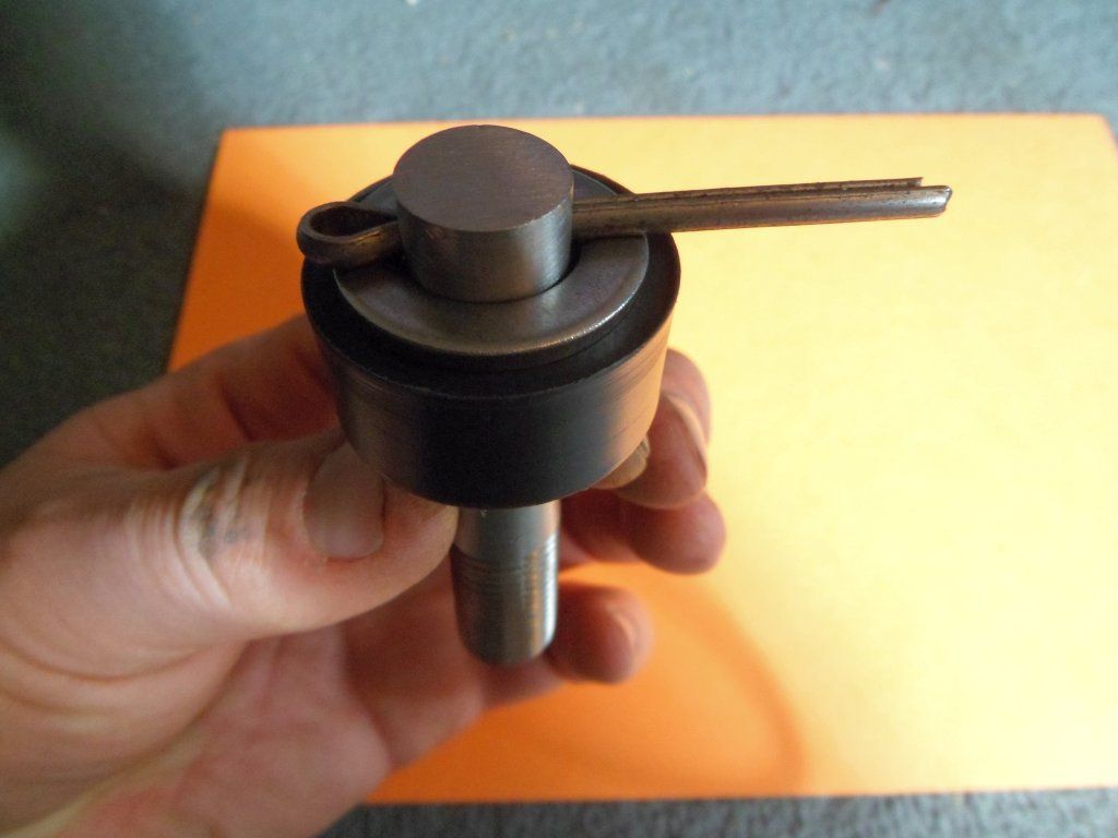
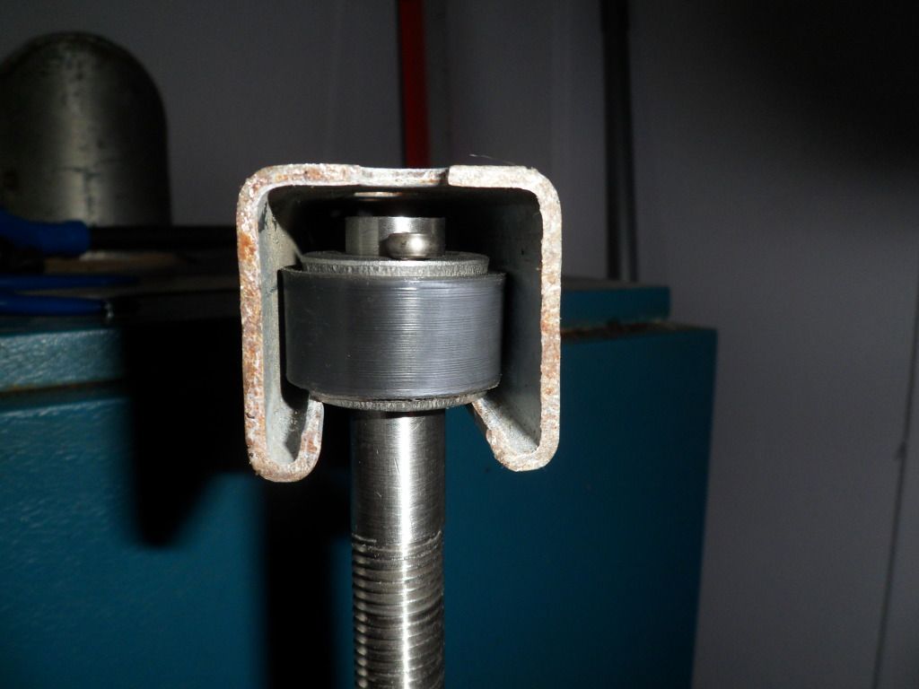
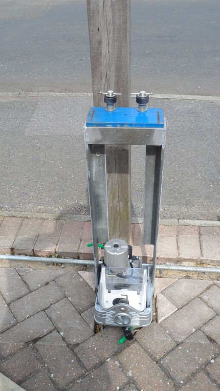
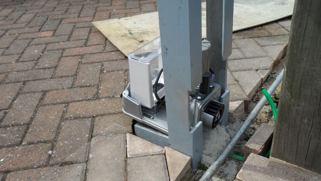
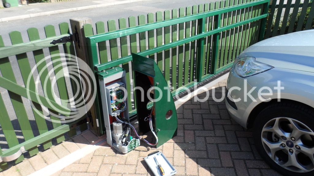
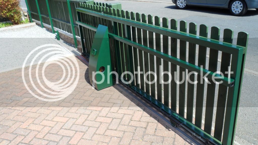
I came up with the idea of using Unistrut as the guide rail and the idea for the motor controls housing based on that hotel in Dubai. I made up the shafts and rollers in stainless & nylatron and supplied the materials for the housing along with various electrical bits and the Unistrut. John used a recycled steel frame he got from work, cut n shut it then added the slats. I left all the builder's work to him. Much coffee and biscuits were gotten through doing this with many fag packet sketches:

Rollers:
SAM_2408.jpg


Sam_2410.jpg


SAM_2414.jpg


Mechanics:

gate029-1.jpg


gate028-1.jpg


Electrics:

SAM_0116.jpg


Finished article:

SAM_0119.jpg


SAM_0120.jpg


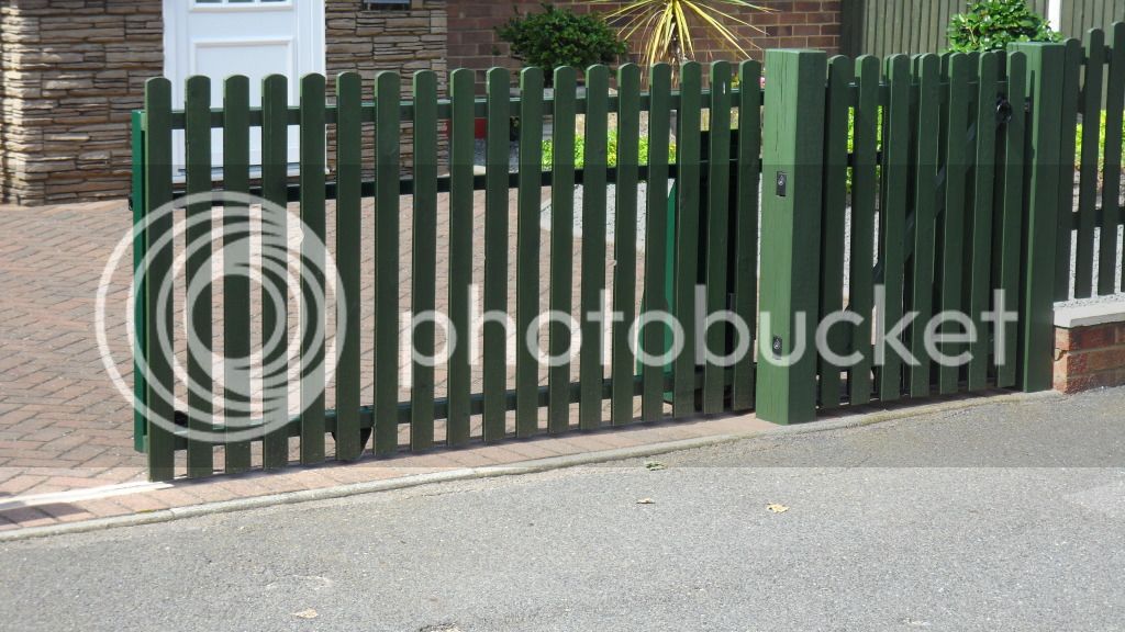
Added a 24VDC break beam so the side gate cuts the sliding gate operation. He wouldn't have the strobe at all to start with so I came up with the idea of placing it INSIDE the enclosure with perspex windows. TBH only really visible at night. Added a genuine FORD switch to one of the blanks on his Focus dash and mounted the transmitter under the dash. It does work very well and look the part IMO. Going to add safety edges shortly.

 
Nice just hope someone doesn't try and come in the side gate whilst main gate is opening or closing

 
Nice just hope someone doesn't try and come in the side gate whilst main gate is opening or closing
On the gate control board is an emergency stop function. Basically you take a board link out and put in your normally closed e/s switch. What we have added is a 24VDC break beam detector that crosses behind the side gate. As soon as the beam is broken it stops the sliding gate dead in it's tracks. (What's a bit odd is that as the side gate opens the first slat that the beam sees stops the gates but then the beam passes through the gap, sees the next slat and so on. Although the sliding gate remains stopped you hear the beam detector clicking on and off as the side gate opens thru it's arc. The gate will only then move again by operating the fob. You can have it I think so that it reverses. To my mind the thing "wrong" with the whole design is that it's too "slatty". Stick your hand in those slats and then it gets pushed against one of the fixed uprights and I reckon it's finger/hand/KID'S ARM breaking time! He is considering sheeting over the slats with clear perspex

 
Very Nice.

I was expecting (don't ask why) a video too (linked to youtube).

 
good work.

i started doing something similar a while back - i made the frame for the gate (and a big gate at that, about 4mtr wide and 1.8mtr high), then lost interest. the frame is still at my unit, chained to the roof girders to keep it out the way.... been there about 3 years now

 
looks like better quality than the average per-fabricated kit i use. iv always thought about using unistrut this way but never really connected how to make up the right size rollers etc! very impressed, for the mechanically less experienced of us do you mind me asking for a more broken down explanation on what the rollers are made of and formed etc?

 
looks like better quality than the average per-fabricated kit i use. iv always thought about using unistrut this way but never really connected how to make up the right size rollers etc! very impressed, for the mechanically less experienced of us do you mind me asking for a more broken down explanation on what the rollers are made of and formed etc?
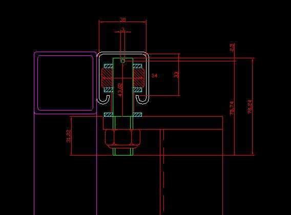
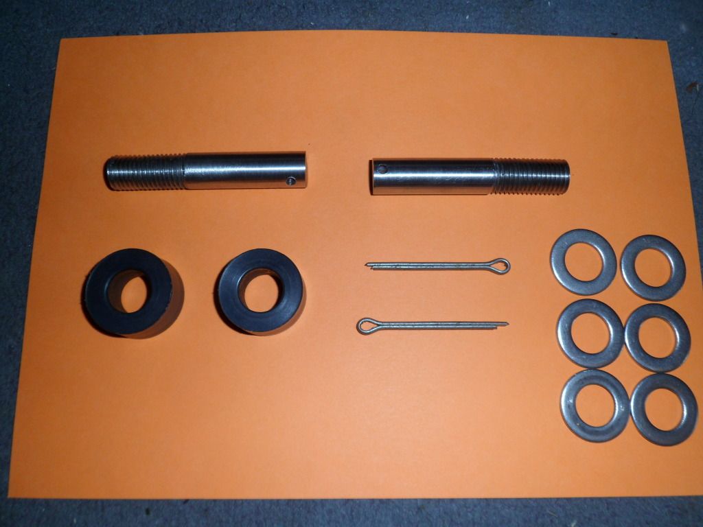
OK, initially measured up the unistrut, drew it on CAD and worked out what would "fit". The roller shafts are made from 16mm diameter stainless steel bar. Cut to length with a grinder then finished off in the lathe (actually I think I might have just cut and filed these ones square). Then I put an M16 coarse metric thread on the end (M16x2.0) using a hand held stock and HSS split die. The shaft ends were then held in a vee block and cross drilled using HsCo (cobalt) drills to suit the split pins (again stainless steel). The black rollers are made from Nylatron - in effect graphite impregnated nylon so self lubricating to a degree. Start off with an over size lump in the lathe, drill up the middle to clear the M16 shaft, turn down the outside diameter to that required and part off to length. Ordinary nylon would do as the rpm is real slow and it's as much a guide for the unistrut as a roller. Add a few M16 flat round stainless and nylon washers and job done. I could probably figure a way to use a stack of nylon washers in pace of the Nylatron actually...........

NOT that I did a mechanical and production apprenticeship! ;)

 
Last edited by a moderator:
Found a rough cad drawing I did with some dimns on showing the unistrut in relation to the rollers:

ust.jpg


Should have mentioned that the "spacer" under the roller was a bit of 20mm galv conduit.

 
Last edited by a moderator:
Top