Growatt CT discrepancy.

Talk Electrician Forum

Help Support Talk Electrician Forum:

This site may earn a commission from merchant affiliate links, including eBay, Amazon, and others.
Status
Not open for further replies.
so 50 watts is far better than 250 watts ..................

It sure is.. :)

And using the same analogy, 0 watts (or even -watts) is better than 50 watts.

btw. I'm not unhappy the way the system is working, I'm maybe been a little bit nit picking, but if this can be changed with some simple register settings, then why not try.. :)
 
Well there is no 'of course' about it, it could configured for zero export in which case you end up with a small import all of the time.

Just trying to help.

Sorry, the of course wasn't meant to be snubbish.
 
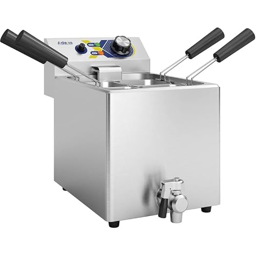
Recently I've had a Growatt inverter installed, most things work really nice, one issue that seems to be very common is the reading you get from a Smart meter are not the same as what the Growatt inverter is saying, from what I can gather this is due to CT clamps not been totally accurate.

eg. When Growatt believes it's exporting 0 watts, the Smart meter says about 50 watts usage, this seems pretty consistent too. So of course the outset of this, it that there is a trickle of 50 watts import all day, this of course can add up over a year, I'm on Octopus, so during the night I can charge batteries so I don't want to be exporting any during the day, unless I have surplus from my solar panels.

Now replacing the CT for a Meter really seems overkill, when all that needs to be done is the Growatt inverter just compensates for this 50 watts.. I've searched all over the internet to see how, what seems like a very trivial thing to configure, but Growatts documentation is not very good here :(.

But during my search I did find this -> https://www.photovoltaicsolar.in/Growatt_Manual/MAX Series Modbus RTU Protocol.pdf

You can see that register 1038 . bCTAdjust CTAdjust enable, looks exactly what I'm after, but of course this is just a flag to say to enable a CTAdjust, but what I can't work out is what register & values do you set for the adjustment. The next 4 registers 1039-1042 look like it might have something to do with it, but with them not saying CT I'm really not sure. Or are these register just not what I think they are?..
Did you get to the bottom of this problem? I have just got round to looking at mine which is also using about 50watts even when the batteries are full and able to meet all my demand.
 
I too am interested if this was resolved. Would using a smart meter be any better at low current than a CT? I also wondered if there is a difference in turn ratio between CTs and how you tell the SPA that ratio? Perhaps it doesn't matter as it just tries to make the reading zero, I have a non-growatt CT which is why I mention this.
 
CTs are just not accurate at low currents, which is why they bounce arround. The meter fixes this. But as John has mentioned on other posts. The meter responds a bit slower. I prefer the slower meter and having the in home display read 0 most the time.
Putting more turns through the ct can help but then you need to compensate in the inverter config, not sure how on Growatt.
 

Attachments

  • image.jpg
    image.jpg
    1.4 MB · Views: 0
I have just had an SPH5000 and 2x GBLI6500's installed. I also have 20-90w parasitic drain back to the grid, but this isn't constant. It looks like random little humps on the graph. Every now and again it will also export 40w in the same fashion. I have read in the Inverter manual that the CT clamp should be within 15m (cable length) of the inverter and a meter can be up to 100m length. My inverter is in the loft and meter in the cupboard on the ground floor running in an "L" shape on the ground floor and outside wall and then back in the loft which is more like 20m i would say. I wonder if this length of cable is affecting things. What's everyone else's cable lengths to the CT? I am seriously considering getting a meter as i want to export and import when i want to. Not by accident...
 
I have just had an SPH5000 and 2x GBLI6500's installed. I also have 20-90w parasitic drain back to the grid, but this isn't constant. It looks like random little humps on the graph. Every now and again it will also export 40w in the same fashion. I have read in the Inverter manual that the CT clamp should be within 15m (cable length) of the inverter and a meter can be up to 100m length. My inverter is in the loft and meter in the cupboard on the ground floor running in an "L" shape on the ground floor and outside wall and then back in the loft which is more like 20m i would say. I wonder if this length of cable is affecting things. What's everyone else's cable lengths to the CT? I am seriously considering getting a meter as i want to export and import when i want to. Not by accident...
Just check if the export limit has been enabled in the settings.
 
Just check if the export limit has been enabled in the settings.
The export limit is set to off. As far as i am aware i would need a meter to enable this and for it to work. Why would this feature affect the parasitic draw from the grid?
 
The export limit is set to off. As far as i am aware i would need a meter to enable this and for it to work. Why would this feature affect the parasitic draw from the grid?
If export limit is on and set to zero for example, the inverter cannot increase it's voltage to get to zero export, it will only get close to it. If export is enabled, the inverter can deviate around zero a little export, a little import etc. The control within the inverter being digital does not have infinite steps, internally if it set it's voltage so that a small import is occurring, it then increases it's output by one digital step in the control system could then result in export. That is what I believe is occurring, I've closely monitored my SPH6000 and can see this happening with the output voltage.
 
Did you get to the bottom of this problem? I have just got round to looking at mine which is also using about 50watts even when the batteries are full and able to meet all my demand.

No, I did email Growatt and got a reply.

Was asking for serial numbers etc, so kind of pissed me off a bit. I shouldn't need to do that, the setting on MY Growatt inverter should be something "I" can do and change, not an employee of Growatt. I can understand some settings might be damaging to adjust, but altering CT calibration settings shouldn't be one, and if I need to do it again in the future it shouldn't need another email to Growatt.

Anyway, I've emailed yet again for some information on calibrating CT clamps, and if I get some info I will post here. Maybe more people emailing Growatt might help here. Really not sure why adjusting CT clamps has to be so secretive or hard to do. Real wattage = CT watts + X, or even better (CT watts + X) * ScaleFactor. You get then idea..

Another gripe!!, server.growatt.com is a nice site for viewing status etc, but it should also be something that can be self hosted, I don't like this reliance on a 3rd party website to control my inverter, if this company gets hacked / goes bust / just stops supporting the product etc, who knows what's going to happen etc.

For the above, I'm a programmer so for collecting data I suppose I could use grott -> https://github.com/johanmeijer/grott only issue here is that it's only for reading from what I can tell, but in theory should be able to write register settings as that's what Growatt server can do, so another idea is just use a Raspberry PI and talk direct to the modbus, with that I can then read stats & write register settings. Bonus not having issues with Growatt server timeouts and get faster updates. Of course none of this helps with the CT clamps not been calibrated correctly as that's obviously a register setting inside the inverter that Growatt seems to be secretive about, or just can't be arsed to document it..
 
Could it be a combination of the CT clamp and the inverter response to demand/load? There has to be some lag in the provision of load and I assume the grid provides the buffer? Adding some chart data to support this - my parasitic is low - maybe 5-10w. When the batteries are charged and solar is exporting, then it is zero. In the transitions, at 10am for example, there is a small draw from the grid and again when we lose the sun later in the afternoon. Am on Octopus Go hence the 0030-0430 draw.

An expansion to the original query that is potentially linked to CT accuracy, if I may, why does the growatt chart show zero import from the grid when clearly there is an import (orange)?
Locked to prevent being resurrected (again)
Octopus 14 May 23.pngGrowatt 14 May 23.png
 

Attachments

  • Growatt 14 May 23.png
    Growatt 14 May 23.png
    428.6 KB · Views: 0
  • Octopus 14 May 23.png
    Octopus 14 May 23.png
    117.5 KB · Views: 0
Last edited by a moderator:
Status
Not open for further replies.

Latest posts

Top