Knightrider..........for Gates!

Talk Electrician Forum

Help Support Talk Electrician Forum:

This site may earn a commission from merchant affiliate links, including eBay, Amazon, and others.
In the link below under "Choosing a suitable NPN transistor", having trouble determining what "Load resistance RL" is for these for the 10mm LEDs I have. Just stuck a basic multi-meter across one and aside from it lighting up a bit all I can tell is it's above the 2K of the meter's range.

Is RL then for these going to be "a given" or is it something measured?

http://electronicsclub.info/transistorcircuits.htm

Apologies, though I've been building kits since a kid my underpinning knowledge of electronics is a bit lacking! More a case of monkey see / monkey do! Thinking this, but not sure as to what resistor to put on the BASE between the i.c. output pin and transistor:


Last edited by a moderator:
I'm VERY rusty on component level design these days, but, I am determined to get back up to speed.

On the face of things your calcs seem fine so far.

IIRC, the next thing is to choose your transistor.

A guess would be a BC109 or similar, or equivalent.

Remembering that if you have a lot, it may be cheaper/easier to get a DIL package of several and breadboard it?

Once you have sized your transistor then you can sort the base voltage/current/resistance to power it up.
Cheers. About 40p each for a BC109C

http://www.cricklewoodelectronics.com/Cricklewood/home.php?cat=183

I'm sure I have a few kicking around in one of the many component draws!

 
Last edited by a moderator:
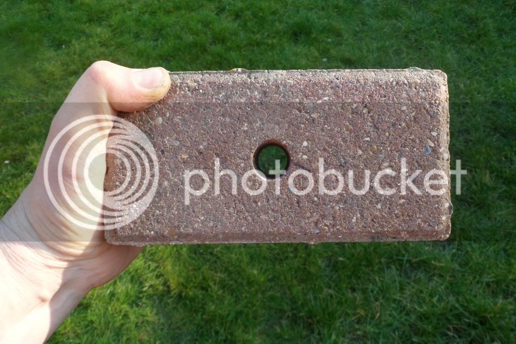
Enough of the math! Had a go at drilling a paving block and they're 'kin HARD! I've cut plenty with a disc cutter but trying to drill one was new.

Used a 20mm tungsten carbide edged holesaw from Toolstation (73155). Tried in the pillar drill to start with and got about 1/4" in. Gave up, stuck it in the Makita cordless on hammer and that got through it but at the expense of the holesaw and arbor drill! And I kept it reasonably cool with water too.

At this rate it'll cost £3.23 JUST to drill each hole (from S'fix a similar holesaw is £9.50 but I dare say better quality)! Still, it's neat enough:


Last edited by a moderator:
Hmmm........had a beer and another look at the math. Says "the transistors minimum current gain hFE (min) must be at least x5 the load current Ic divided by the maximum output current from the IC"

                               load current Ic

hFE(min) = > 5 x   ---------------------

                               max IC current

For a BC108C it has an hFE of 420 and an Ic.Max of 100Ma. Back then to the calc:

                                load current Ic                                                                                                          0.1

hFE(min) = > 5 x   ---------------------  so, taking the IC's max output current as 4mA we get   5 x   --------------------- = 125

                               max IC current                                                                                                          0.04

Thus, the BC109C having an hFE(min) of 420 exceeds 125 so all's good on that front

Then to calc an approx. value for the base resistor, RB the calc is:

          Vc x hFE

RB = ----------------  where Vc is the supply voltage (9V in this case)

             5 x Ic

Putting the numbers in I get:

            9 x 420

RB = ----------------

            5 x 0.1

RB = 7560 Ohms (so an 8.2 KOhm resistor will be nearest).............I think?

STILL though can't get my head around RL in the calc:

                              supply voltage Vs

load current Ic =  -------------------------

                              load resistance RL

(I WAS originally assuming in the calc above Ic is 0.1A and Vs is 9V but then noted it's NOT Ic(Max) so thinking Ic is in fact 0.02A as in the 20mA for the LED)

If that's the case then I've satisfied the "the transistors maximum collector current Ic(max) must be greater than the load current Ic". That is 20mA vs 100mA.

??? RL for a relay's a given (I think) as in the coil resistance but the 10mm LED with the series resistor how does that come into it all?

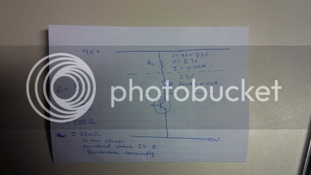
Or have I already figured this as in 285Ohm for RL (270 or 300 nearest standards actually) and 8.2KOhm for RB? Sorry to be a numpty!!!

 
Last edited by a moderator:
Erm...........IGNORE post #27..........think I've got my Ic & Ic(Max) confused in calculating hFE(min) & RB Should have used 20mA instead of 100mA in both calcs! Think it works out as 189K for RB........

 
Who said breadboard it?

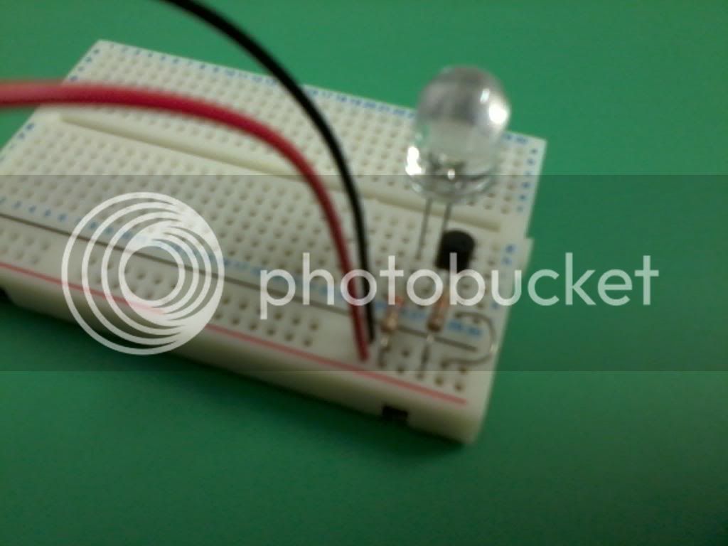
Anyway, finally figured the calcs; 270 ohm for the LED and 18K on the transistor base. LED bright enough that your eyes go funny for half an hour!


I haven't used a plain shank masonry bit since I got my battery SDS!  :coat
I guess then I'll have to try a 20mm SDS thru another block tomorrow then! But not tonight...........a couple of beers in and I'm about to start soldering the kit but I'll leave out the original red LEDs and associated resistor.

I'm then going to rig ALL 8 ultra bright LEDS on the breadboard and jump across from the kit PCB.

Wondering if, as the furthest LED will be about 10-12' away from the PCB I'll get any voltage drop. Maybe lower the protective resistor value to account for volt drop?

 
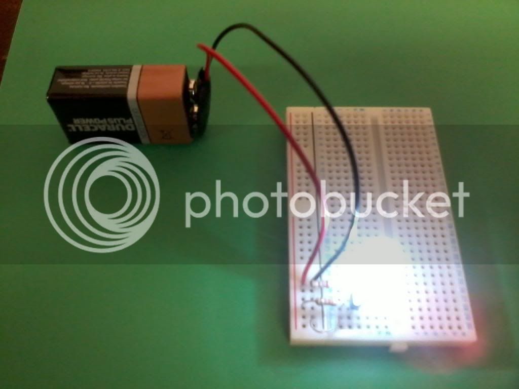
Taken on my old Samsung 2MP phone so excuse the quality but you'll get the drift! Knocked it up this evening after a couple of beers tbh. Found 20A fuse wire great for interconnecting between the original kit and the breadboard.

Uploaded a little video (for some reason to the boy's account). Only put 4 LEDS on at the moment - will drive 8 in total. They're as bright as..........well, ultra bright LEDs (quite blinding in fact). I've actually dropped the LED resistors from the calculated 285 ohm to 220 ohm.

https://www.youtube.com/watch?v=jN5xucuAH_4

One button to reset / turn on and off. Then a "PROGRAM" button with a few effects.

Will tidy up / case etc. At least it's a basis to go on and the transistor circuit is doing it's job!

 
is that using that little maplin board?

I like it,  :D
Yes, it's the "chaser" kit that Richard suggested above. From what I can figure though the chip used a CD4015 only puts out 2.6mA per output..........so I'm using that to switch a transistor to handle the bigger load 20mA 10mm dia ones.

Will build a separate PCB to take the transistors and associated resistors now I know it works on the breadboard.

(Easy once I figured the maths!)

 
Last edited by a moderator:
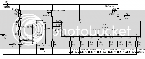
OK, here's the ORIGINAL circuit:


(Quite impressed with that  fotoxx for editing images in Ubuntu btw)

So, the circuit..........I've ditched the R1 to R8 3k3 resistors and original, on board LEDS. Instead I've put in 18k resistors in (for R1 to R8) and these switch the new transistors via their BASE input. All works well.

A couple of things;

At the mo I only have outputs Q1A to Q4A connected up............the chasing effect runs from left to right, pauses then starts again from left to right. I WAS hoping for a back and forth effect.............I wonder if this will kick in when Q4B is in place i.e. the "8th" LED?

Then, need this to start automatically as in when power is applied...........said above about placing a low value cap across the supply start button.........any idea of value etc?

Cheers

 
Last edited by a moderator:
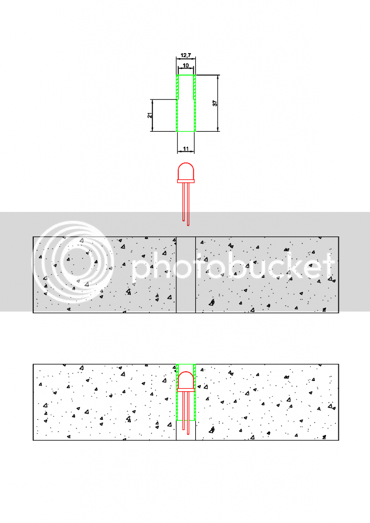
Plan for making the LED "inserts" as in I have some stainless steel 1/2" diameter tube that already has a 10mm hole up it. Just need to open to 11mm to accept the LED. Then solder the wires in and fill up with clear 2-pack epoxy:


Erm.......

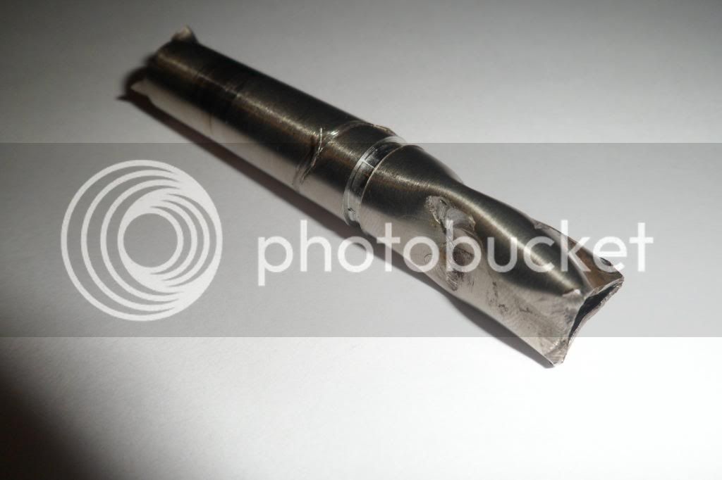
So off I went to the neighbour's freezing cold barn wearing the head torch and fired up his lathe (involves holding the boost button on the 3-phase converter etc). Managed to drill out the 10mm bore to 11mm x 21mm deep a treat. Then I attempted to part the thing off to length with the tool I found already fitted............at least it all happened at low revs! Beer o'clock now and try again over the weekend  Guinness


Top