streetlighter
Senior Member
Hey guys thought i would indulge you in some of my recent works for my assessment!
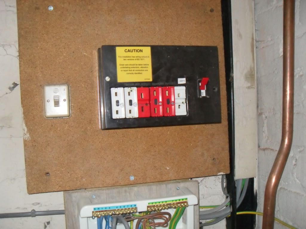
4 Bed Semi Detached Property TNCS Arrangement
The original install contained an old Rewireable C/U
http://i1182.photobucket.com/albums/x453/kayandbert/gobble118.jpg
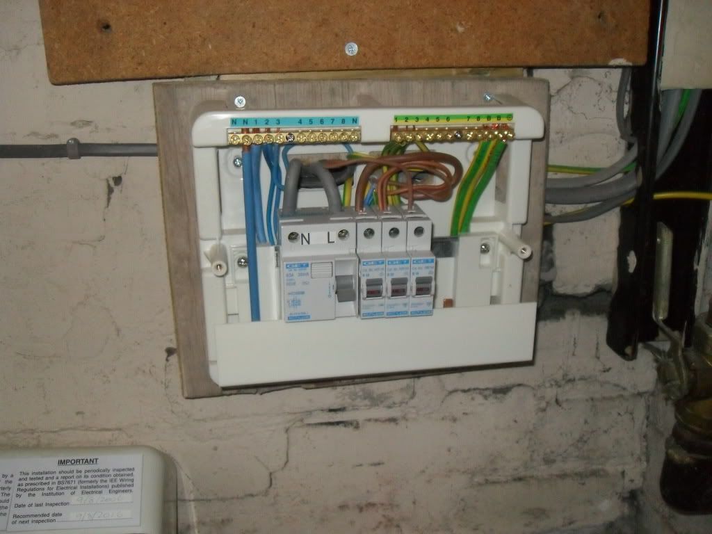
and altered in 2006 to extend the install to contain an Extension this was using a GET C/U
http://i1182.photobucket.com/albums/x453/kayandbert/gobble119.jpg
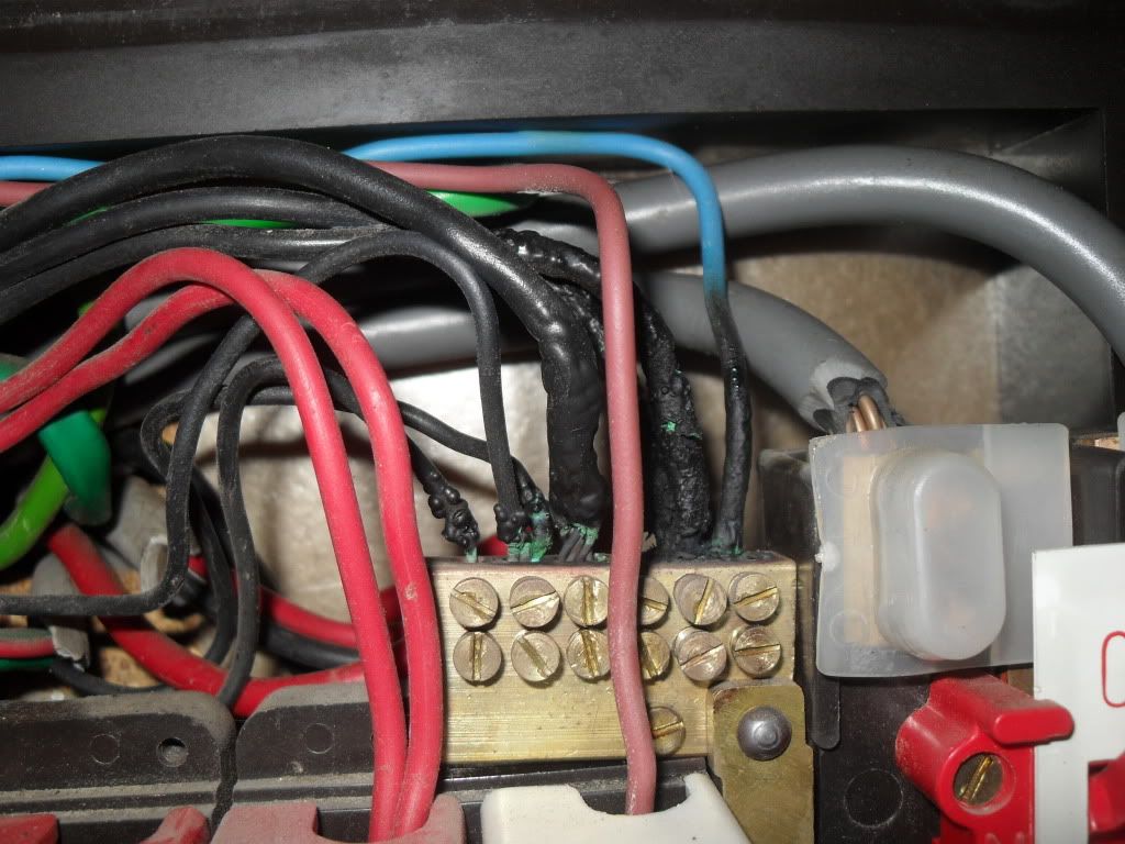
Its a good job i was planning this upgrade as when i opened the unit today i found that the board has been burning up quite bad! owing to the previous electrician leaving loose terminals inside the original rewireable.
http://i1182.photobucket.com/albums/x453/kayandbert/gobble120.jpg
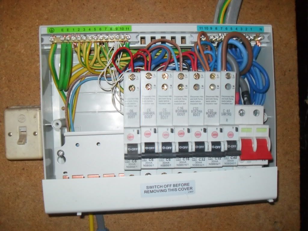
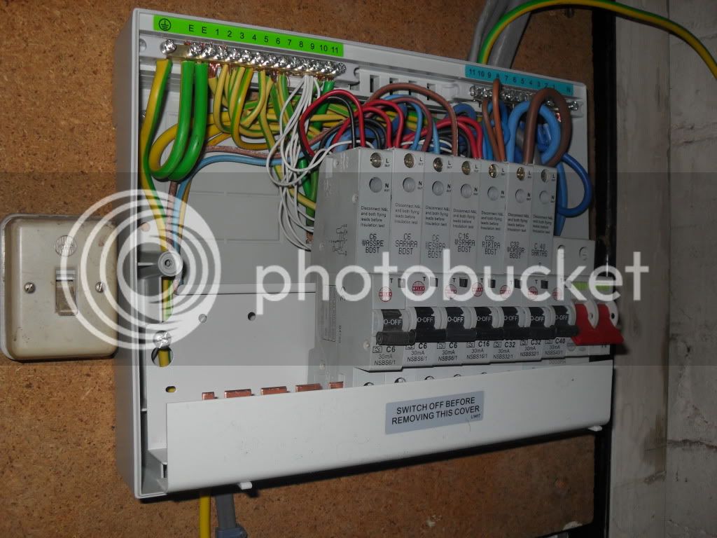
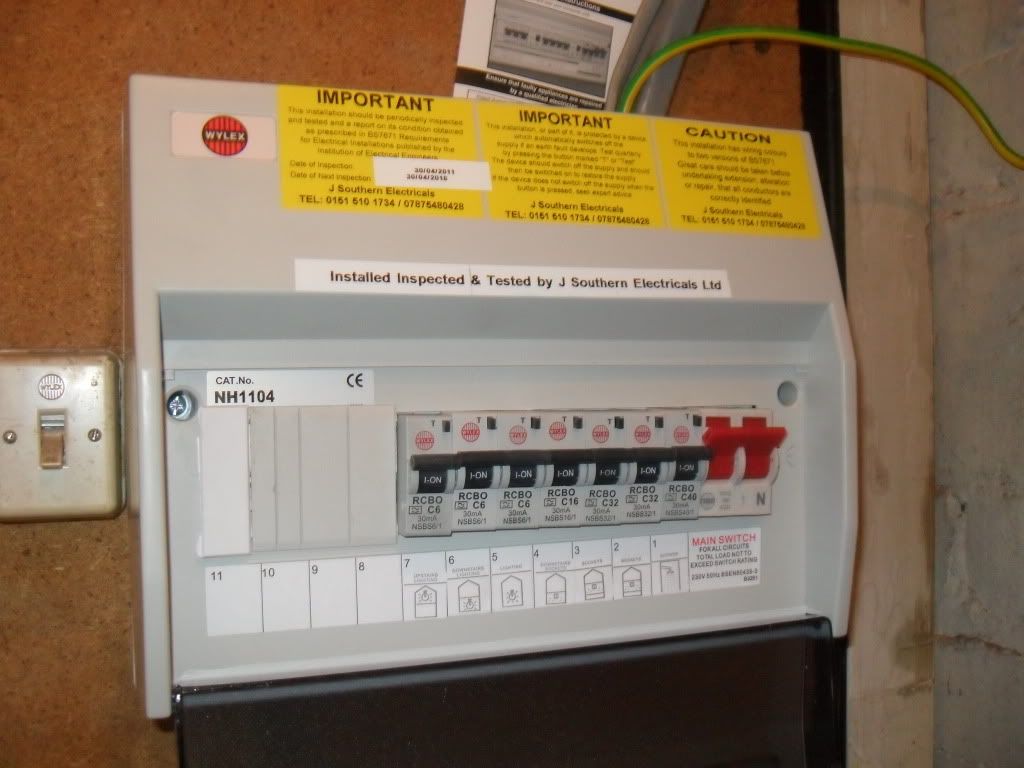
I planned on replacing the 2 boards using a Wylex 11 Way Unit and RCBO's
and combining the 2 Consumer Units into 1.
http://i1182.photobucket.com/albums/x453/kayandbert/gobble121.jpg
http://i1182.photobucket.com/albums/x453/kayandbert/gobble122.jpg
http://i1182.photobucket.com/albums/x453/kayandbert/gobble123.jpg
http://i1182.photobucket.com/albums/x453/kayandbert/gobble124.jpg
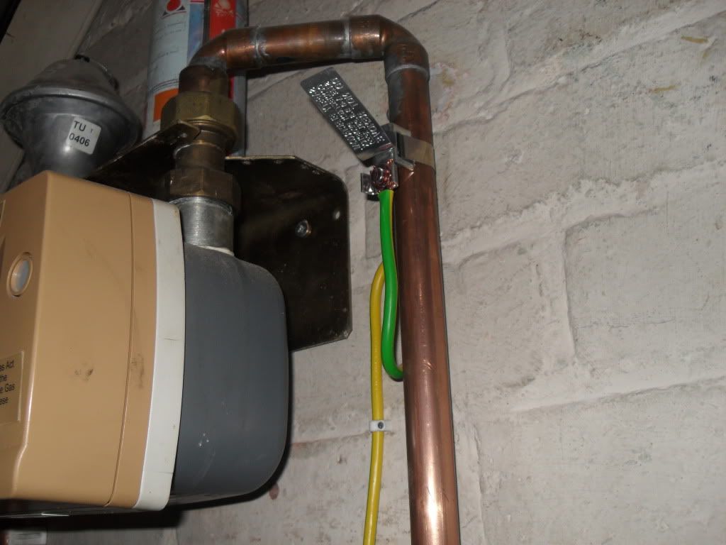
i also reformed the Main Bonding Conductor as it looked like it was lashed in!
http://i1182.photobucket.com/albums/x453/kayandbert/gobble130.jpg
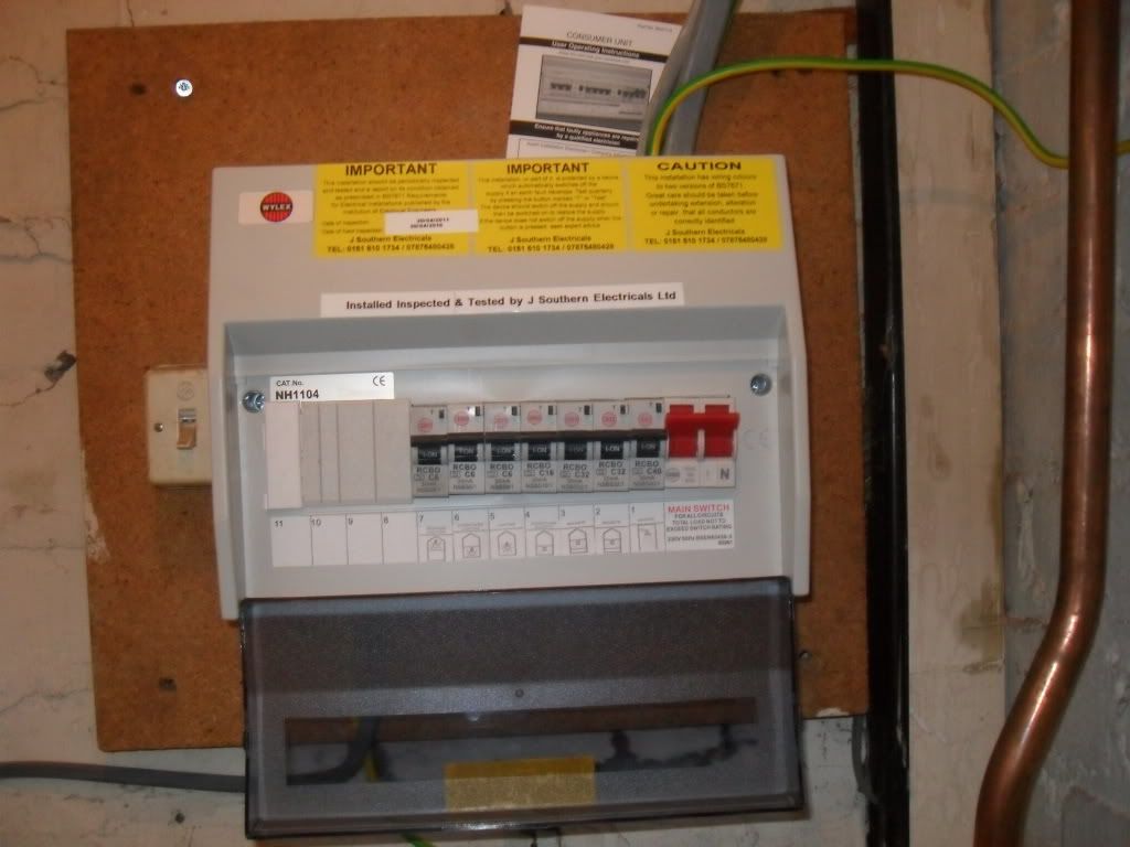
The installation looks much better and im sure you will all agree much safer for the customer! ANNNND it now complies with the 17th Edt
i hope this is ok for the assessment
4 Bed Semi Detached Property TNCS Arrangement
The original install contained an old Rewireable C/U
http://i1182.photobucket.com/albums/x453/kayandbert/gobble118.jpg
and altered in 2006 to extend the install to contain an Extension this was using a GET C/U
http://i1182.photobucket.com/albums/x453/kayandbert/gobble119.jpg
Its a good job i was planning this upgrade as when i opened the unit today i found that the board has been burning up quite bad! owing to the previous electrician leaving loose terminals inside the original rewireable.
http://i1182.photobucket.com/albums/x453/kayandbert/gobble120.jpg
I planned on replacing the 2 boards using a Wylex 11 Way Unit and RCBO's
and combining the 2 Consumer Units into 1.
http://i1182.photobucket.com/albums/x453/kayandbert/gobble121.jpg
http://i1182.photobucket.com/albums/x453/kayandbert/gobble122.jpg
http://i1182.photobucket.com/albums/x453/kayandbert/gobble123.jpg
http://i1182.photobucket.com/albums/x453/kayandbert/gobble124.jpg
i also reformed the Main Bonding Conductor as it looked like it was lashed in!
http://i1182.photobucket.com/albums/x453/kayandbert/gobble130.jpg
The installation looks much better and im sure you will all agree much safer for the customer! ANNNND it now complies with the 17th Edt
i hope this is ok for the assessment
Last edited by a moderator: