C/U Change for Elecsa Assesment

Talk Electrician Forum

Help Support Talk Electrician Forum:

This site may earn a commission from merchant affiliate links, including eBay, Amazon, and others.

streetlighter

Senior Member
Joined
Feb 25, 2008
Messages
327
Reaction score
0
Location
Widnes Chehsire
Hey guys thought i would indulge you in some of my recent works for my assessment!

4 Bed Semi Detached Property TNCS Arrangement

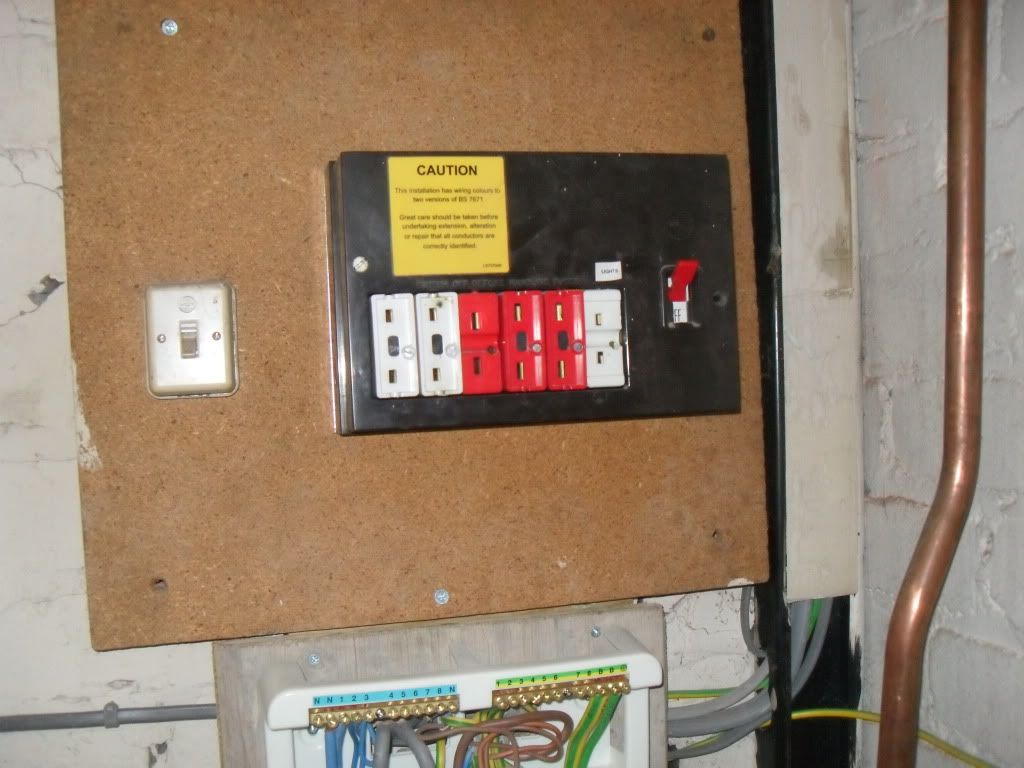
The original install contained an old Rewireable C/U

http://i1182.photobucket.com/albums/x453/kayandbert/gobble118.jpg

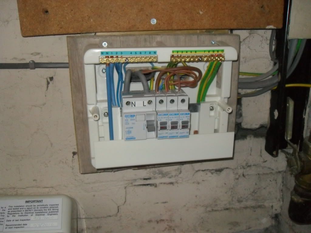
and altered in 2006 to extend the install to contain an Extension this was using a GET C/U

http://i1182.photobucket.com/albums/x453/kayandbert/gobble119.jpg

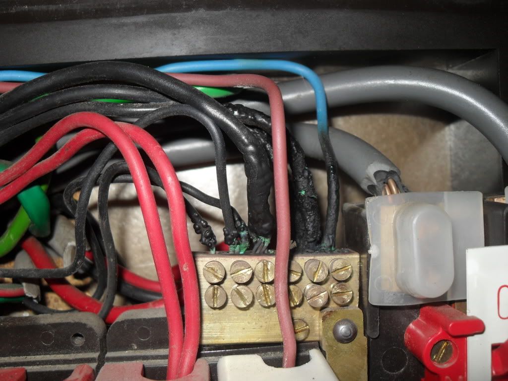
Its a good job i was planning this upgrade as when i opened the unit today i found that the board has been burning up quite bad! owing to the previous electrician leaving loose terminals inside the original rewireable.

http://i1182.photobucket.com/albums/x453/kayandbert/gobble120.jpg

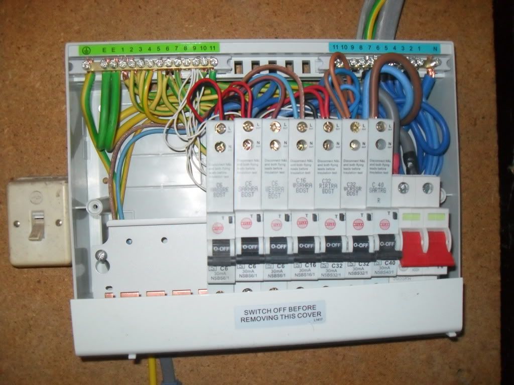
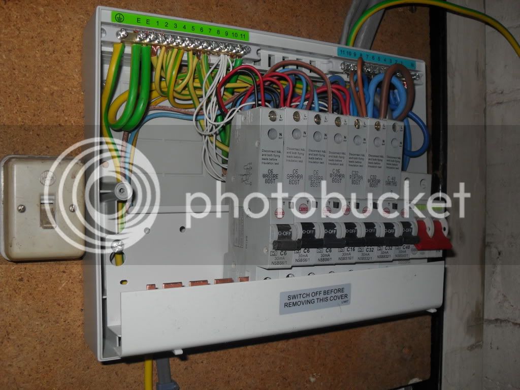
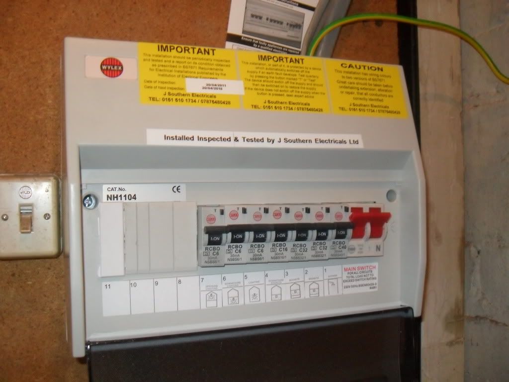
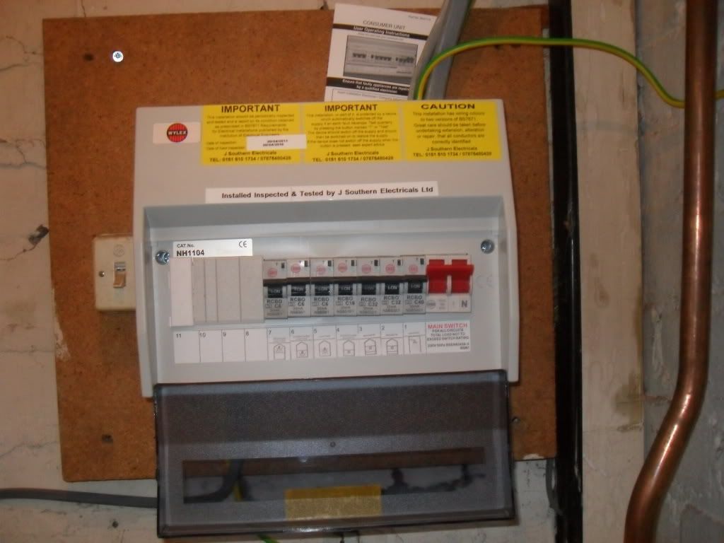
I planned on replacing the 2 boards using a Wylex 11 Way Unit and RCBO's

and combining the 2 Consumer Units into 1.

http://i1182.photobucket.com/albums/x453/kayandbert/gobble121.jpg

http://i1182.photobucket.com/albums/x453/kayandbert/gobble122.jpg

http://i1182.photobucket.com/albums/x453/kayandbert/gobble123.jpg

http://i1182.photobucket.com/albums/x453/kayandbert/gobble124.jpg

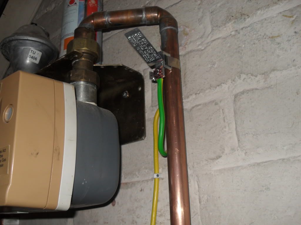
i also reformed the Main Bonding Conductor as it looked like it was lashed in!

http://i1182.photobucket.com/albums/x453/kayandbert/gobble130.jpg

The installation looks much better and im sure you will all agree much safer for the customer! ANNNND it now complies with the 17th Edt

i hope this is ok for the assessment :D

 
Last edited by a moderator:
Hey guys thought i would indulge you in some of my recent works for my assessment!4 Bed Semi Detached Property TNCS Arrangement

The original install contained an old Rewireable C/U

gobble118.jpg


and altered in 2006 to extend the install to contain an Extension this was using a GET C/U

gobble119.jpg


Its a good job i was planning this upgrade as when i opened the unit today i found that the board has been burning up quite bad! owing to the previous electrician leaving loose terminals inside the original rewireable.

gobble120.jpg


I planned on replacing the 2 boards using a Wylex 11 Way Unit and RCBO's

and combining the 2 Consumer Units into 1.

gobble121.jpg


gobble122.jpg


gobble123.jpg


gobble124.jpg


i also reformed the Main Bonding Conductor as it looked like it was lashed in!

gobble130.jpg


The installation looks much better and im sure you will all agree much safer for the customer! ANNNND it now complies with the 17th Edt

i hope this is ok for the assessment :D
Edited it for you

---------- Post Auto-Merged at 23:22 ---------- Previous post was made at 23:18 ----------

You got there before me:( :( :(

Nice job except I hate drunk MCBs!

And jeez that CU is tight for RCBOs

Are you Zs ok for C type MCBs??

 
Soz mate the missus uploaded the pics for me and fluffed it up and used the HTML instead of the direct link!

they where straightend up after pics where taken and they not MCB's :p

i agree on the fact it was a little tight for RCBO's but i had them in stock and i was doing it for cost of parts as its the missus grandaparents that are the customer! anyting was better then what was in there!

yeh Zs is well within the boundaries the Zs reading came through at 0.89 ohms and that was the highest reading from all of the RCBO's.

 
Looks ok the Wylex tall metalclad consumer units have a bit more space for RCBO's. Manfacturers have not yet got round to making decent room consumer units for RCBO's unless you use the Denmans basic ones. I think you should have no problems on your assessment looking at the pics.

 
You've put the "switch off before removing this cover" sticker in the wrong place :D

To see it you need to remove the cover.............

:D

They'll fail you for that, you know.

 
Apache, I can concur with that, I use wylex all the time, its factory fitted,

streetlighter, where do you get this idea that the highest Zs is fine? 0.89 ohms is way too high for a 40A type C .! 0.46 ohms is max allowed, do you actually know your maxes and what did you actually get on your tests?????

---------- Post Auto-Merged at 00:59 ---------- Previous post was made at 00:54 ----------

oh, and inadequate labelling,

ccts, 2 , 3 & 5

---------- Post Auto-Merged at 01:00 ---------- Previous post was made at 00:59 ----------

what is the earthing arrangement?

and I hope you filled in the top knockout where the cables enter.

 
If you've only got 7 circuits why do you have cpc's in no's 1 to 7, 10 &11 and all the earth fly leads in no 9?

 
Looks like the old M.E.B`s in 10 and 11 to me.

You will need to crimp a ferrule on the end of your RCBO earth fly leads and terminate them individually with their corresponding cpc`s

 
Apache, I can concur with that, I use wylex all the time, its factory fitted,streetlighter, where do you get this idea that the highest Zs is fine? 0.89 ohms is way too high for a 40A type C .! 0.46 ohms is max allowed, do you actually know your maxes and what did you actually get on your tests?????

---------- Post Auto-Merged at 00:59 ---------- Previous post was made at 00:54 ----------

if you re read my post i actually said the highest Zs out of all of my tests for each circuit was 0.89 ohms and that was for a 6a Type C RCBO the 40a Type C tested at 0.38 ohms. i do know my maximums tho i simply put the highest reading that was obtained from the all 7 circuits!

oh, and inadequate labelling,

ccts, 2 , 3 & 5

circuits 2,3,5 all have adequate labelling demonstrating on the lable which circuit they are demonstrated by the pic on the label,

---------- Post Auto-Merged at 01:00 ---------- Previous post was made at 00:59 ----------

what is the earthing arrangement?

the earthing arrangement is TNCS

and I hope you filled in the top knockout where the cables enter.
the top knockout where the cables enter the CU complies with IP2X as there is no way any fingers or tools can get down inside!

---------- Post Auto-Merged at 09:57 ---------- Previous post was made at 09:53 ----------

raindy your right i have all the existing M.E.B's in 10 and 11 and all the Fly Leads in 9 this doesnt matter as it is a functional earth therefor allowing 1-7 containing CPC's

 
I think the others like to see them in with their corresponding cpc`s only and not all bunched together and the ends crimped with a ferrule

 
Streetlighter, the top of a CU needs to be IP4X (1mm piece of wire if I remember correctly), it's the sides and bottom that can be IP2X.

 
can guarantee that nothing can fit through that knockout on there it was a 2nd thought at 1st to use a 2nd knockout then i figured that this would need sealing so i used the 1. nothing is getting down through that knockout! a dust particle would give up and go elsewhere

 
Nice one streetlightier, good luck with the assessment.

 
streetlighter,

Realle speaking the rcbo functional earths should be in the same terminal as the circuit earth, for identification purposes, electrically it does not make any difference.

Also as you have x no of white wires and no numbers to positively identify the functional earth could mean removing all of them and tracing them back to the actual rcbo, where as if they are with the corrsponding circuit earth they are easily identified.

Bootlace ferrules correctly crimped, i.e. not with a pliers (not saying you would, but I have seen it done!) on the ends is good as the wire is finely stranded and is thus easily broken with the sort of screw terminal in a cu.

 
Only problem I can see is that the main earth appears to be the same size as the bonding conductors i.e. 10mm. If that is the case, unless you are happy to explain the sizing to your assessor using the adiabatic equation, I would change it to 16mm to comply with table 54.7.

Cheers. Chris

 
Top