Drill Motor - Am I Missing Something?

Talk Electrician Forum

Help Support Talk Electrician Forum:

This site may earn a commission from merchant affiliate links, including eBay, Amazon, and others.

OnOff

Mad Inventor™
Supporting Member
Joined
Dec 25, 2011
Messages
5,468
Reaction score
78
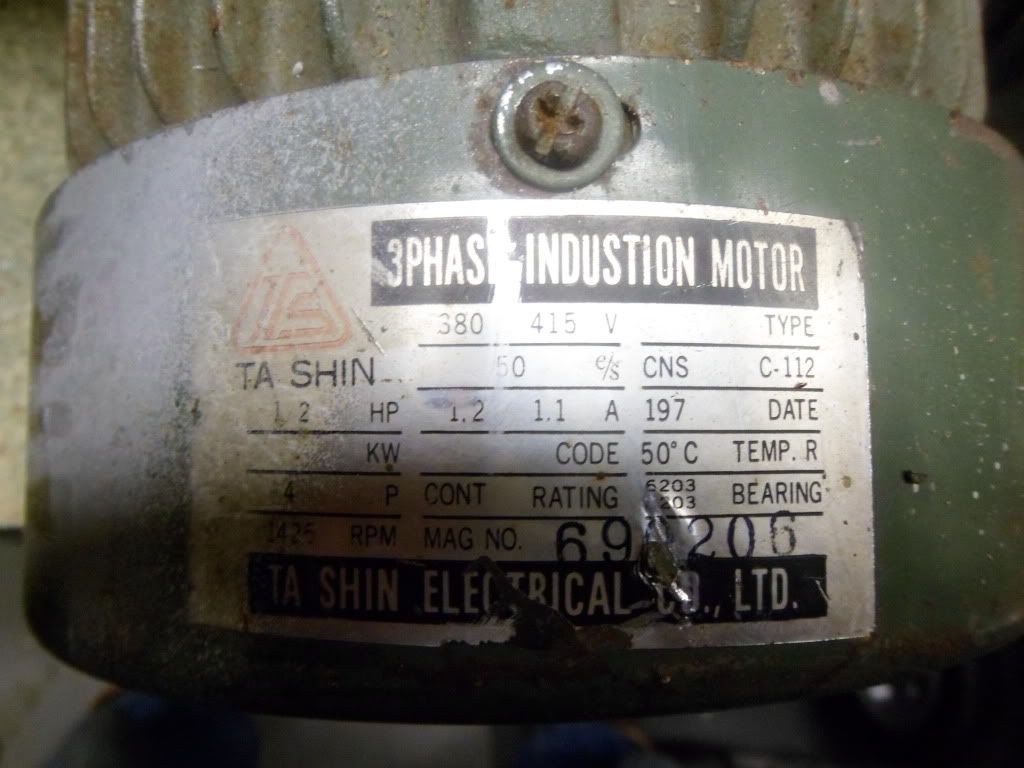
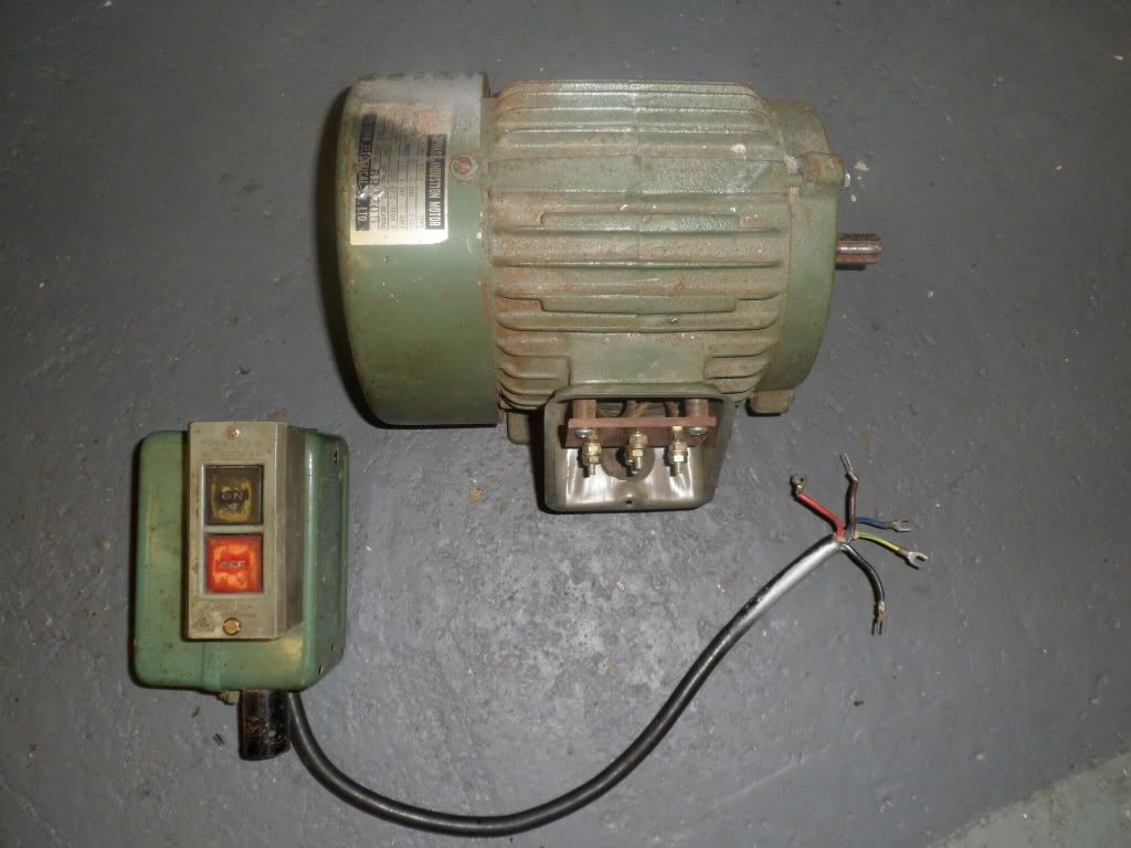
I've just been given a 3-phase pillar drill. Real nice, old heavy duty thing with 5/8" chuck, rack & pinion rise and fall made by Atlas. Anyway, the mate who gave it to me had removed the motor with the intention of fitting a single phase motor - he never did so it sat there until he got fed up with it and asked if I wanted it. Fitting a single phase motor is an option but the motor shaft is 5/8" diameter. The small jobbies from say Machine Mart have either 14mm or 19mm shafts so I either need to have the stepped pulley machined or make a sleeve if I go for a 14mm shaft.

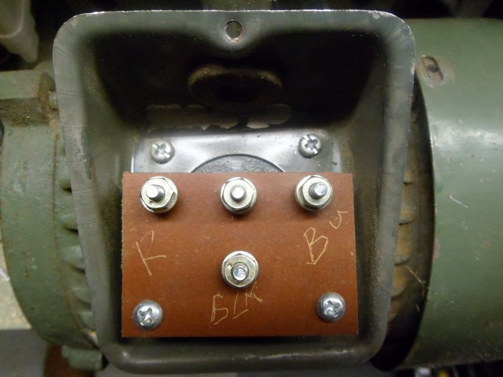
So.........I got to thinking about using it "as is". I've always fancied having a dabble with running 3-phase kit off of single phase and have a couple of books on simple phase conversion. BUT something has me stumped. I took the motor terminal cover off and see 4 connections. I'm only used to "modern" 6 terminal motors that you can wire star or delta. There are 4 wires coming up to these (one on each). I get approx 50ohms between any two of the 3 windings so assume it's hard wired for delta. It's the BLACK wire that has me stumped. It doesn't appear to connect to anything - either the case or any of the windings. Also the black is cut back in the push button contactor starter. Assuming then that I'm missing something very obvious and will shortly feel a total numpty! Any assistance appreciated!
SAM_3505.jpg


SAM_3504.jpg


SAM_3502.jpg


Is there a brake on the motor, as its a bench drill maybe.Some brakes are 230V.
I'm used to seeing a brake release handle (on braked motors). Don't think this is one. Will take a look tomorrow and have the end cap off. Cheers. :good night:

 
Worth starting this thread just for that link! Great stuff.

---------- Post Auto-Merged at 09:51 ---------- Previous post was made at 09:44 ----------

The only way you will find out it to take the ends off and see where the wire goes, if it goes into the windings and you have to know then strip the windings out, its chinese so could be anything to be honest....
Yep, off to the garage in a while, end caps off and try and dig out the star point. Before the kids emerge and we have to "take them somewhere". Wondering if you can use a delta wired motor to build a rotary converter........thought they had to be in star? More reading of Electric Motors, Workshop Practice Series, books 16 & 24 I think!

....and to think some people go abroad for their holiday, what's that like?

 
I thought you said it was wired in delta ?Anyways that 4th terminal on a chinese motor is normally the star point and they sometimes bring out 1 wire (not three) and go though a klixon (thermal cutout switch) buried in the windings, the fact you have no connection there could just be a faulty klixon - or i could be part p ing into the wind....
Sorry, my mistake! Was reading one of the books about taking the end cap off to find the star point (if hard wired star) and posted without brain in gear. Yes pretty sure it's delta. Was late last night when I was looking at it after a couple of Buds and the coffee hadn't kicked in yet this morning. Awake'ish now so will go have another look and report back!

---------- Post Auto-Merged at 10:18 ---------- Previous post was made at 10:12 ----------

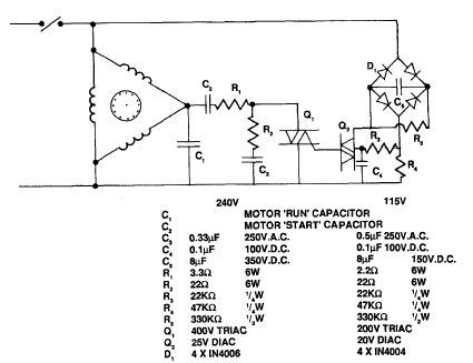
IF the motor is already hard wired delta then I was thinking of something like this triac starter circuit. Might have to seek advice on the triac and diac specs. I'll probably get most of the bits from Cricklewood Electronics:

triac.jpg


Erm...........I took the terminal plate off and there isn't anything connected to the "black" terminal! Sorry about that all. That would explain why I was getting nothing on it when measuring! Straightforward delta wired motor.

Guess the moral is "dig deeper before posting and only dig / post sober!". Still, I did get the Airport link out of it!

(Also just found a bigger motor I'd forgotten I had. Again an old 3 wire jobbie 1.5kW Crompton Parkinson & again "hard wired" for delta).

 
Hi All,

I built a phase converter once, still have it actually.... All i can say is that it worked FANTASTICALLY well... I even solved the problem of the motor you want to run having to be a dual voltage one!!! Took AGES sitting on the bog to figure out, but i did it!!!!

If anyone is interested i will take some photos and post them!!

Finally, the stuff you read in all the books about the sizes of capacitor needed are total crap, much much too large.... I had next to perfect voltage balance between phases too!! It really was great!!

Some of the wiring methods were a bit dubious [read dangerous] but it was only a prototype which ended up being rather more permanent!!!!

Learn from me..... DO NOT fit single phase motors, they are TOTAL crap, make a converter and you will be SOOOOOOOOOO pleased you did!!!!!!!!

john....

---------- Post Auto-Merged at 18:27 ---------- Previous post was made at 18:23 ----------

HI Again,

Like the electronic circuit diagram, trouble is, it will only work with a motor wound for 230V...

john....

 
Hi All,I built a phase converter once, still have it actually.... All i can say is that it worked FANTASTICALLY well... I even solved the problem of the motor you want to run having to be a dual voltage one!!! Took AGES sitting on the bog to figure out, but i did it!!!!

If anyone is interested i will take some photos and post them!!

Finally, the stuff you read in all the books about the sizes of capacitor needed are total crap, much much too large.... I had next to perfect voltage balance between phases too!! It really was great!!

Some of the wiring methods were a bit dubious [read dangerous] but it was only a prototype which ended up being rather more permanent!!!!

Learn from me..... DO NOT fit single phase motors, they are TOTAL crap, make a converter and you will be SOOOOOOOOOO pleased you did!!!!!!!!

john....

---------- Post Auto-Merged at 18:27 ---------- Previous post was made at 18:23 ----------

HI Again,

Like the electronic circuit diagram, trouble is, it will only work with a motor wound for 230V...

john....
Cheers for that, guess I really need a motor wireable for 400 star or 230 delta!. Any info you have on your phase converter I'd be very interested in. Cheers.

 
Oooh right!!!

Well, it is a bit dark to take a photo now, but i will tomorrow... But first, how to get around the "motor wound in delta" problem..

Now, this took lots of sitting on the bog to work out, and if you choose to do it, you do it at your own risk!!! and, if after reading this you have a hernia laughing, then do not blame me!!!!!

I have seen people say, why don't you use a power tool transfomer the "Wrong way around" Well, it will not work that is why!!! Try it, it will just blow fuses.....

Soooooo... Now, i am NOT an electrician, but i do have a bit of knowledge, so here is what i did...

Take yourself a yellow power tool transformer. Take the sockets off the front. Now, so far as i can remember, i disconnected the earth from the transfomer core and used it to go DIRECT to the converter [the tranny is all plastic so who cares!!]

I cannot remember if i disconnected the CTE bit in the centre of the secondary too, i rather think i did.....[was YEARS ago] Anyway......

Now, what you must do is this; You got your neutral and line feeding the primary, yes?? Now, join one end of the SECONDARY to the line end of the PRIMARY

You now feed your converter neutral from the the neutral that is connected to one end of your PRIMARY and take your line from the other end of the SECONDARY.

What you have done, is you have converted your "ordinary transformer" into an "auto transformer"

Instead of REDUCING the 230/240V to 110V it will now ADD the 110V to the 230/240, so now you have got 340/350V Not perfect, 380 would be nice, but it works!!!!!!!!!!!!!!!!!!!!

If you have the secondary the wrong way around, you will still have 230V just swap the wires around.

If you are barking mad enough to do this, it is up to you!!!! But hey!!!!! Full marks to newbie me for thinking it up eh!!!!!!!!!!!

Next you need an idler motor to make your rotary converter bit. I used a 7.5hp 415V star wound motor from an old miller i had here once.

Tomorrow i will dig the converter out, and take some photos, and tell you what size caps i used!!!

I would make a video of the machines running on it, but i have converted my transformer back to "normal" now!!!

I used it for about a year on my power hacksaw, and a clarkson tool grinder, and i can honestly say that there was NO difference in the running compared to "proper" three phase, [i got three phase now!]

It worked UNBELIEVABLY well, FAR FAR FAR better than single phase motors....

You run a machine with a single phase motor on it, then fit a three phase one, and there is a huge difference in the smoothness it runs, plus all your starters, reversing switches, etc will work properly. I converted a few machines to single phase, worst thing i ever done.... Just cost me an arm and a leg to convert them back.....

here is the motor i used as an idler anyway.. I was fitting new bearings at the time!!

View attachment 4090

john...

 
Last edited by a moderator:
Top