2330. L2. Unit 203 (3). Fluorescent Lighting Assignment

Talk Electrician Forum

Help Support Talk Electrician Forum:

This site may earn a commission from merchant affiliate links, including eBay, Amazon, and others.

Bane

Senior Member
Joined
Oct 17, 2008
Messages
215
Reaction score
0
Hello people.

Firstly I would like to apologise if these topic has already been covered. I've had a quick perusal and didn't come across anything that may help on the site so, here I am asking for your help please.

So, I have an assignment coming up and I've been told it'll be based upon a fluorescent circuit. We shall be taking results and interpreting data gained and so forth.

I'm pretty confident on how a fluorescent light works and how the current flow differs from initial start up to operation. I feel confident on naming components of the circuit also.

What I would like to ask are the following:

1) Why do voltages not add up to supply voltage?

Is it because they are out of phase? The current lags the voltage because the choke/ballast is an inductive component of the circuit? Also,due to the circuit being in series, the current remains the same but the voltage divides?

2)The Capacitor reduces current and increases the Power Factor. Is this a capacitive component whilst the tube is a resistive component?

3) What does current lagging voltage and voltage lagging current actually mean?

Now some 3 Phase questions please:

1) On a STAR system the LINE and PHASE current (IL and IP)remains the same but the LINE and PHASE (VL and VP) voltage differ. So I am correct in assuming the following:

IL=IP

VL= 1.732 x VP

VP= 1.732/VL

2) Measuring VP (PHASE VOLTAGE) is measuring between any Phase and Neutral? So you would normally expect a reading of 230v on an equally balanced load?

3) Whilst measuring VL (LINE VOLTAGE) is measuring between any 2 Phases? Again, you would expect a reading of 400/415v?

4) Finally, what would be the recommended SAFE ISOLATION PROCEDURE on a 3 Phase sytem? (I have found a few procedures but some seem to contradict the others)

Thank you all for taking the time to look and, hopefully, help.

 
Sorry, also forgot to add, under the fluorescent lighting section:

The formula for Inductive Reactance: XL = 2 x 3.14 x f x L

The formula for Capacitive Reactance: Xc = 1 divided by 2 x 3.14 x f x C

Where f = Frequency (Hertz)

L = Inductance (Henrys)

The formula for Impedance: Z = Division by R squared + (XL -Xc) squared

also: Z squared = R squared + (XL - Xc) squared

Note: If Xc is larger than XL then calculate (Xc - XL)

If the circuit contains no capacitance then Xc = 0

If the circuit contains no inductors then XL = 0

Power Factor, True Power, Apparent Power also.

How would all the equations factor into my fluorescent assignment? Sorry if I'm being thick and, if you think that I am going to struggle without knowing these answers, please do not be afraid to tell me so.

Many thanks again.

 
Hi Bane

1) Why do voltages not add up to supply voltage?
The choke voltage added to the lamp voltage do not add up to the supply voltage as the choke is an inductor and the voltage and current are out of phase. Draw a right angled triangle and put resistive voltage on one side(the lamp voltage), inductive voltage on the second side(the choke voltage) and the hypotenuse will be the supply voltage. It doesn't work out perfectly as the choke has a resistive element and is not a pure inductor.

The addition of the capacitor give the opposite effect on the current to the inductive choke and brings the current closer to being in phase with the voltage (yes this is pf correction)

As explained by msb2003 or check out thread where this came from

http://talk.electricianforum.co.uk/showthread.php?p=57225#post57225

1) On a STAR system the LINE and PHASE current (IL and IP)remains the same but the LINE and PHASE (VL and VP) voltage differ. So I am correct in assuming the following: IL=IP

VL= 1.732 x VP

VP= 1.732/VL
thats how i understand it as well.

4) Finally, what would be the recommended SAFE ISOLATION PROCEDURE on a 3 Phase sytem? (I have found a few procedures but some seem to contradict the others)
http://www.select.org.uk/downloads/publications/Select%20-%20Safe%20Isolation%20Procedures.pdf

www.niceic.com/inc/file-get.asp?FILE=BPG2_March07(sec).pdf...

should get you going...

 
Thanks PoorFish.

Done and dusted.

I went way too deep into the assignment. Turned out I didn't need to know half the stuff I'd revised for anyway. College seems to be really good at that. They'll tell us we need to revise such a thing then when the exams/assignments come up, the questions are nothing to do with what we've covered.

Thank Kev for Swindon Massive is all I can say!

Will let you know what result I gained next week.

 
This should be the Unit 204 not the Unit 203. For future reference, This is covered on the forum. I made a point in saying be careful with the wording of your answer to Q1.

The Best answer (And would have Guaranteed me a Distiction" is what "msb2003" posted in post number 2 here:

http://www.talk.electricianforum.co.uk/showthread.php?t=4138

 
We are Talking about these ones?!

Fluorescent_Luminaire_Vs_CandG_2330.gif


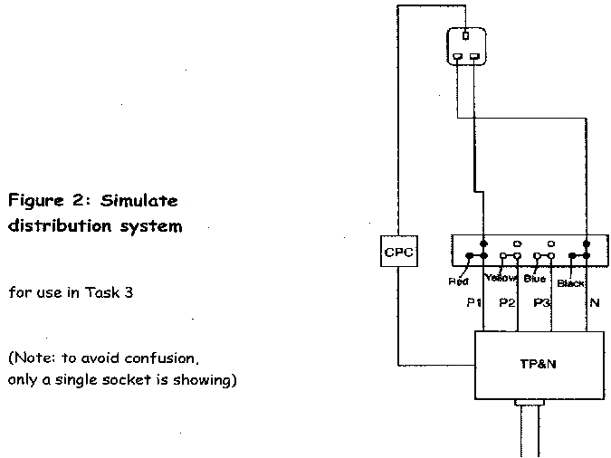
Similated_Distribution_System_CandG.gif


Hi Admin.

You mention Unit 204 NOT 203.

I was using swindonmassive and my college's reference points.

There doesn't seem to be a Unit 204 for some unknown reason though Unit 205 is also known as Unit 4 weirdly enough!

Anyway, that is splitting hairs.

Your last post with the two diagrams?

Well figure 1 is exactly what we had. We also had to label the components and interpret test results. Volts, Amps etc. The only thing is, EVERYTHING was clearly labelled for us.

So basically all you had to do was read your assignment and everything you needed was already there for you (spoonfed basically).

Figure 2 was not included.

Thanks again Admin, Poorfish and msb2003 for all your help.

Hopefully I shall receive my assignment next week then if anyone needs any help I may be able to proffer guidance.

Oh, almost forgot. Gained a Distinction!

 
well done on the distinction.

I done the 301 this week and got a credit....im well happy with it though my run of distinctions has come to an end!!!

As you may have heard its heavy on motors and i dont really like motors.

You have all that to look forward to .

All the best

Poorfish.

 
Yeah my run of Distinctions came to an end in December. Was one mark short of gaining it! Worse thing is I knew which question cost me it also.

My own fault, I hadn't revised for the exam so should be thankful for my Credit.

As for Motors, quite confident with those as when we're quiet on electrical side of things we're rewinding motors in the other department.

 
We are Talking about these ones?!
Fluorescent_Luminaire_Vs_CandG_2330.gif


Similated_Distribution_System_CandG.gif
Im just doing a bit of revision for the 204 practical & have a question about the fluorescent circuit diagram above.

Could anyone tell me what actual tests need to be done for the practical ?

Im guessing from looking at the diagram that I`ll have to test the current at position A1 & A2, the the voltage at V1 & V2.

I understand the theory of inductors, capacitors, pf correction etc, but im just a little unsure of how much testing I`ll have to do to in the exam.

Cheers.

 
It was my understanding that only dead tests would be done on the 204?

 
You're only allowed to dead tests on any of the modules on level 2 or 3. (H&S carp again).

The 2330 is the same course that the 16 Year olds do (Full Time), and they aren't allowed to do them either.

I did live testing at my college though.

 
Not sure,

im presuming that the tests will be to show different current readings (with & without a capacitor)

Have you done the 204 yet Bane ?

 
We`ve been told live testing will be done in year 3 and on our AM2 (final practical exam)

 
Admin,

how would you go about proving the effects of the capacitor etc, if its all dead tests ?

Or am I making it more complicated than it actually is ?

Cheers

 
Not sure,im presuming that the tests will be to show different current readings (with & without a capacitor)

Have you done the 204 yet Bane ?
No. Shall be doing it end of May. I think the tests are:

1) Continuity of main/supplementary bonding conductors

2) Continuity of cpc's

3) Polarity

4) Insulation Resistance

 
Just found a pdf for the 204 on the C&G website.

Ive attached 1 of the pages (pdf file is too big to upload - 774K),

Reading through this it sounds like its gonna be live tests,

Anyone else done the 204 & 206 lately ?

Cheers

204 practical.jpg


Latest posts

Top