Hello people.
Firstly I would like to apologise if these topic has already been covered. I've had a quick perusal and didn't come across anything that may help on the site so, here I am asking for your help please.
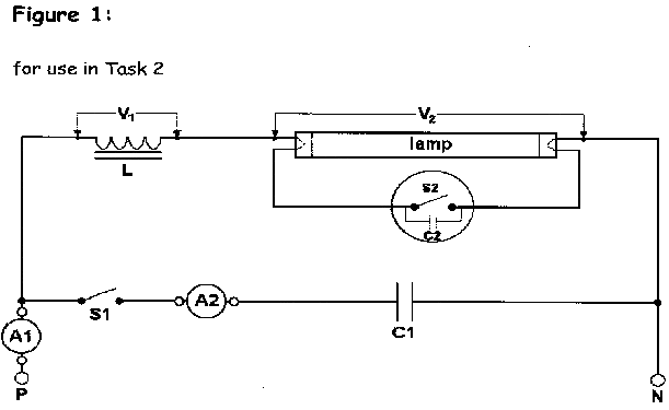
So, I have an assignment coming up and I've been told it'll be based upon a fluorescent circuit. We shall be taking results and interpreting data gained and so forth.
I'm pretty confident on how a fluorescent light works and how the current flow differs from initial start up to operation. I feel confident on naming components of the circuit also.
What I would like to ask are the following:
1) Why do voltages not add up to supply voltage?
Is it because they are out of phase? The current lags the voltage because the choke/ballast is an inductive component of the circuit? Also,due to the circuit being in series, the current remains the same but the voltage divides?
2)The Capacitor reduces current and increases the Power Factor. Is this a capacitive component whilst the tube is a resistive component?
3) What does current lagging voltage and voltage lagging current actually mean?
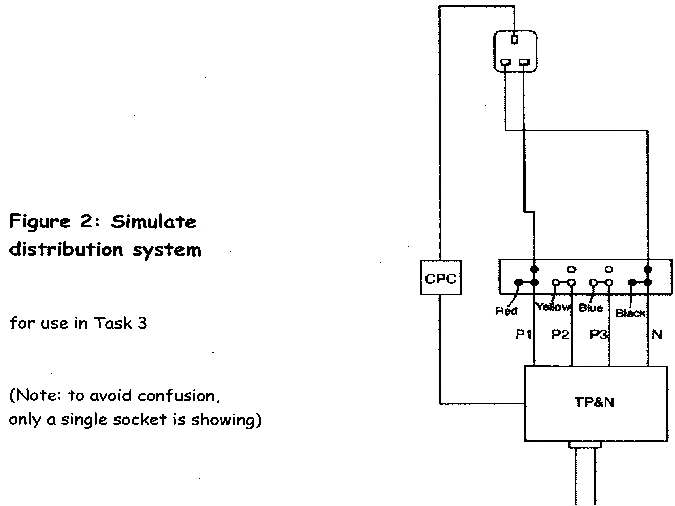
Now some 3 Phase questions please:
1) On a STAR system the LINE and PHASE current (IL and IP)remains the same but the LINE and PHASE (VL and VP) voltage differ. So I am correct in assuming the following:
IL=IP
VL= 1.732 x VP
VP= 1.732/VL
2) Measuring VP (PHASE VOLTAGE) is measuring between any Phase and Neutral? So you would normally expect a reading of 230v on an equally balanced load?
3) Whilst measuring VL (LINE VOLTAGE) is measuring between any 2 Phases? Again, you would expect a reading of 400/415v?
4) Finally, what would be the recommended SAFE ISOLATION PROCEDURE on a 3 Phase sytem? (I have found a few procedures but some seem to contradict the others)
Thank you all for taking the time to look and, hopefully, help.


