Push-fits vs Crimps

Talk Electrician Forum

Help Support Talk Electrician Forum:

This site may earn a commission from merchant affiliate links, including eBay, Amazon, and others.
Larnacaman,They may be standard elsewhere in the world, but I have yet to identify a recognised standard in the UK that recognises these values, anyone can call anything whatever they like, and often do!.

However standards and legislation are there to ensure clarity of communications.

I can't find a UK standard referring to MV.

I await to be corrected, sorry buddy.

Here's hoping...
Just take a look around the suppliers of MV, ...or as you still call it HV equipment, switchgear, cables, transformers in the UK ....ALL without exception will be calling it MV, ....NOT HV!!! ...I know because i've been doing my own checking after your previous post.

It all came about some years ago now, and it will probably come under an EN number because it was part of the combining of EU standards thing. (can't remember the correct term.)

But i can assure you those in the industry in UK will be calling that voltage band MV and Not HV!!! Don't get me wrong, old habits die hard and i still often call it HV myself, ....but not in written form, where i always refer to it's correct term of MV!! ...lol!!!

 
Good work my man!

Perhaps we all can continue this in a friendly constructive manner to glean more info and experiences.

I have a few levers I could sacrifice, however, it is you who should do the experiments!

I think I also have a few spring balances in the van for belt tensions, I'll check to see what I have.

The one thing that KME suggested is a slow steady pull this is because jerk is the 3rd derivative of distance and this imparts disproportionate force to the connections.

If you do the maths you'll see what I mean!

 
I'll add my 2p's worth in here.

Good experiment patch and to me it shows both methods to be strong enough for their useage. The deciding factor over which is better, is down to reliability, ease to install and cost. Which for me they are pretty much equal, with the wago's being a little easier but more on the cost.

As for reliability, I suppose it depends on the installation, I know I have before pulled apart crimped terminations, a couple being my own (thats what the mechanical checks for) but I've never pulled apart a wago when doing the tug test. These terminations are designed for fixed wiring which has little stress on the cables once installed. Personally I like wagos, so so easy to use, no human error involved. If we're talking HV or bigger cables then obviously its a different kettle of fish.

 
UPDATEI'm glad I started this thread, even if it's just because of the copious discussion that ensued! I spent ten minutes in my shed this evening having a quick play regarding some of the criticism.

1. KME suggested some cheap crimp pliers may not be fit for purpose and have smooth jaws.

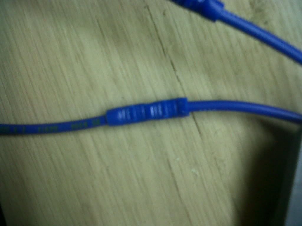
That is not the case here. The jaws are clearly ribbed and you can hopefully see from the following close up.

IMG00087-20101228-2238.jpg


2. It was suggested that the crimp pliers may require adjustment.

I have adjusted them so they are crimping at their maximum tightness. I have quite a collection of tools and although they are at the cheaper end of the market they do 'feel' decent enough quality. It is a reputable company I bought them from, not a DIY shed special.

3. Sidewinder said that the blue crimp is the correct size for 2.5mm cable either single core or stranded.

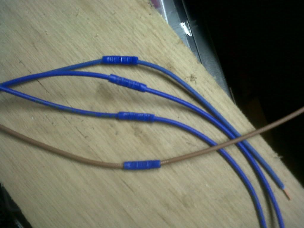
I made up four more lengths of cable, two stranded and 2 solid core - all 2.5mm2 using blue crimps. Today I didn't heatshrink as it added time, I was cold and I had run out of lighter gas! Furthermore I don't believe it adds anything to the strength of the joint [suppose adhesive lined heat shrink may].

IMG00088-20101228-2238.jpg


4. Sidewinder and KME pointed out that the crimp was being pulled in a linear manor and the push-fit at 90
 
Graham,

The crimps should meet all necessary requirements for these connections as they are sold by a reputable global supplier into this market.

However, as per my earlier post, some crimps are more equal than others!

As far as the physics go think materials science also with regard to a solid copper core being crimped against a stranded core with the same crimp and tool.

 
Maybe its another negative on the crimps, too many variables with getting the right tool with the right crimps.

 
Sellers,

This I felt, though re-reading my original post may not have been made clear is one of my points.

Crimps are easier to muck up either with dodgy crimps, tools or by user error.

 
I used to work for the MOD (RAF civvy) and used to use a lot of crimp terminations (PTT - Precision Termination Technology) in the aircraft equipment that I used to repair, most of it fast jet in my case.

Ever year we had to do IIRC 6 sample crimps which were sent of to an onsite testing facility - there they checked we were using the correct wire, crimp, crimp tool and crimp tool setting; they also tested the crimp for it's resistance and mV drop; they also did a mechanical strain test to see when the crimped joint failed.

After all these tests were carried out we were certified for the next 12 months to crimp away to our hearts content.... BTW any crimp joints were end terminations in "Hellerman" type plugs, all wires leaving the plugs were loomed using waxed looming cord and there was no strain on the cable or plug/socket.

Before any crimps were made the tool was checked with go/no go pins.

 
Sellers,This I felt, though re-reading my original post may not have been made clear is one of my points.

Crimps are easier to muck up either with dodgy crimps, tools or by user error.
I totally agree mate, but yeah sorry if I missed it, I did only scan read pages 2-4 I switched off due to another HV discussion. ROTFWL

 
nice experiment patch thanks for taking the time to do it. are them red push fits reusable (for some reason i thought that brand were not).

you need a statment at the bottem

no animals were harmed or not given medical attention while i was crimping.

i can here it now,

"sorry the vet cant come out he is in his shead crimmping off.

why you ask to take photos and put them on the internet, hello hello, thats strange they hung up":^O

 
Interesting thread, as I remember starting a thread a year or so ago as I was always told never to crimp single core (solid drawn) copper, still don't but I was educated here that it is done in several applications, consumer units for example. A lot of good points getting raised by all taking part,I personally think there is a time and place for each type of connection.

On a couple of other notes, one application where I can think that cable is welded is, we have a 120mm bare copper cable ring (with rods) going round our switchrooms, from this ring we T 90mm branches to structural steel etc. this T connection is achieved by a CAD weld. A former is placed round the 120mm and the 90mm with the chemicals in it, it is then lit, bit flash and connection made. Remove former, wee clean, job done.

My other 'by the way' point about 25 years ago I remember getting sent on a course with the electricity board to learn how to solder copper cables to aluminium cables, something I have never done since but it was a good course from what I remember.

Anyway as I said interesting thread. Cheers Steve

 
Larnacaman

Yes there are still MV/HV mechanical type (bolted) connections available. There generally used in site situations where it is physically not feasible to use a hydraulic crimp tool. The Yanks like and use them a lot. They also take a lot of expensive void filling compound.What type of welding are you suggesting they would use on a cable termination?? ...All welding methods i'm aware of, produce ''s**g'' as a by-product, and that's the last thing you would want at MV/HV termination!!
http://www.erico.com/public/library/Industrial/LT21680.pdf

 
Exothermic welding, ...Now your talking!! Unfortunately way outside my remit!! From the looks of those cable types, your well into the 66KV and above.

I think that these cadweld people are not telling the full story, It may be a damn good connection, but it's a pity they didn't show what's required after the welding has been completed. For argument's sake that completed weld on pic 5 page 7, will still need the services of an experienced jointer, to maintain the full integrity of both the semi conductive inner coating (blackish looking ring in contact with the conductor in the same pic) and the insulation, without any voids. ....But that would be the case for whatever method of jointing was used...

 
I used to work for the MOD (RAF civvy) and used to use a lot of crimp terminations (PTT - Precision Termination Technology) in the aircraft equipment that I used to repair, most of it fast jet in my case.Ever year we had to do IIRC 6 sample crimps which were sent of to an onsite testing facility - there they checked we were using the correct wire, crimp, crimp tool and crimp tool setting; they also tested the crimp for it's resistance and mV drop; they also did a mechanical strain test to see when the crimped joint failed.

After all these tests were carried out we were certified for the next 12 months to crimp away to our hearts content.... BTW any crimp joints were end terminations in "Hellerman" type plugs, all wires leaving the plugs were loomed using waxed looming cord and there was no strain on the cable or plug/socket.

Before any crimps were made the tool was checked with go/no go pins.
Did the same tests myself last year at MOD crimp tools checked with go-no go gauges and test pieces sent away for verification any that failed crimp tool was binned and replaced with a new one.Crimp tool being used was AMP CERTI

 
been experimenting today... and verified all of patch's first post

test 1: 2.5 solid & 2.5 stranded. (solid has the blue). blue insulated crimp v push fit

DSCF4581.jpg


crimp failed both times. i was actually expecting it to be harder than it was to pull apart

DSCF4582.jpg


test 2: uninsulated crimp v push fit

DSCF4583.jpg


push fit failed. side cover pulled apart on both, allowing conductor to come out

DSCF4584.jpg


DSCF4586.jpg


test 3: above, but with a different push fit. these are slightly more expensive than first test. seemed to require less force to make this one fail than above

DSCF4587.jpg


DSCF4589.jpg


test 4: uninsulated crimp alone

solid took a lot of force to fail. 2 conductors of the stranded failed. it was wrapped around a bar to try and get equal load on all conductors, but looks like it didnt fully happen

DSCF4590.jpg


DSCF4591.jpg


results:

insulated crimps fail quite easily. also note the conductors after being pulled - they are only slightly deformed from being crimped

push fits were fairly hard to fail.

uninsulated crimps were best. very hard to make them fail. also note the solid conductor after its been pulled - very deformed compared to insulated crimp

 
Appreciate that Andy. I have scoobed you appropriately. I'm secretly glad that a proper electricians insulated crimp failed too. :D


Latest posts

Top