some testing help please for consumer unit change

Talk Electrician Forum

Help Support Talk Electrician Forum:

This site may earn a commission from merchant affiliate links, including eBay, Amazon, and others.

jackfrosty

Senior Member
Joined
Feb 24, 2010
Messages
163
Reaction score
0
Hi, im in middle of joining the niceic and for the two jobs i had to do i have changed a consumer unit and added some sockets in another property. For the consumer unit change i have done i was wondering if you could look at the pictures I have attached of the actual consumer unit and my test results and see what you think and any recommendations.

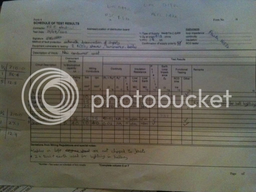
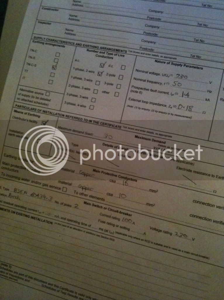
I am going to change the porch socket mcb for a b20 as soon as i can get to senate. Please can you advise me what rcb time do i put in the box 1x or 5x and the highest number i suppose? Also the Ze and PFC i need help with as the PFC seems low?

In the loft the cables have not been clipped to joists and just thrown over, should i just note this like i have done on certificate?

thanks for all your help and advice

consumerunitchange012.jpg


consumerunitchange010.jpg


consumerunitchange001.jpg


consumerunitchange005.jpg


Also i obviously have to do the Zs still, my mind has gone totally blank on how to do this and what setting i put my fluke on, any help most appreciated

thanks

 
That is one messy cert. why all the extra scribbles all over the side? and you need some correction tape for the deviations box

i would put 1x RCD time in the box, and note the 5x in the remarks box

for Zs, test exactly the same as Ze

you have 0.18 as Ze. and 1.4Ka as PFC. what exactly is the problem?

as for cables in loft, i wouldnt mention it

what exactly is meant by '2 T&E used for light'?

also adviseable to have test kit S/N recorded

 
thanks for advice and this is only a rough test sheet, i will transfer onto a new sheet. the reason i thought there was a issue with the pfc as i have seen other test sheets with 16.6ka.

i meant the 2 way lighting in the hallway has been wired in 2x twin and earth instead of 3core and earth, the extra neutral has just been snipped off.

anything else you can see i have done wrong or you would do differently?

thanks

 
I only have a few comments to make...

Main switch is a BS EN 60947-3.. I guess that the number you have put is for the CU as a whole!.. I see it on the label on the CU;)

I would also put the lights on the same RCD as the shower and not the sockets...

Max demand 30A??? I doubt it!!

On the model forms I used to just tick the RCD box (if OK) and then note down all the RCD test results in the comments box adjacent to the relevant circuits

For your Zs box you will have to do a "No trip" Ze or by calc (Zs=Ze+(R1+R2))

HTH

 
is it perfectly acceptable to find the Zs by working it out with Zs=Ze+(R1+R2)

il get the stickers sorted

also how do you know the main switch is a BS EN 60947-3

i will swap the lights with the porch sockets then

if i do a continuity test between the earthing block and the metal work in the bathroom and get a reading of 0.05 or less does this tell me i havent got to supplementary bond?

cheers

 
nic recommend that you should not test Ze if you have to do it at the terminals, it goes agianst HSAW, so they say to calculate it, though i do it and most people do.

also if this is an assesment peice, make sure you dont have copper showing on the mcb's

 
is it perfectly acceptable to find the Zs by working it out with Zs=Ze+(R1+R2)Yesil get the stickers sortedGreat.. don't forget the "safety electrical connection tag at the MET

also how do you know the main switch is a BS EN 60947-3You get to know after a bit;).. do a search for "sector ac22a" and you'll see

i will swap the lights with the porch sockets thenIt's not good having a fault on an appliance taking out the whole house or lights and sockets... best CU is all RCBO, next best is twin RCD and normally people put D/S sockets & U/S lights on same RCD (and opposite on other)

if i do a continuity test between the earthing block and the metal work in the bathroom and get a reading of 0.05 or less does this tell me i havent got to supplementary bond?Reg says if it is effectively connected to the MET and RCD protected then you don't have to supp bond

cheers
Mine RED

 
how do you calculate the ze please?
you cant calculate Ze. but you can get it by enquiry (phone DNO ). but they will most likely tell you the max for that earthing type - by enquiry wont tell you if the sheath has failed and Ze is not 40 ohms. testing will.

 
I would disagree with that,if it was an original on copy then it would be worthless on the CC sheet.
nothing to stop you doing the CC sheet, and then writing on the CC sheet seperately. but now we know there is no need anyway

 
what is the "safety electrical connection tag at the Main earthing terminal"? i thought it was only at earth clamps a tag was required?

 
Hi dan...

just looking at your scedule of test results and was wondering why you had 2.5mm for the 10mm cooker cable cpc. also if the blanks in the c.u are covering unused ways on the busbars then your connection sequance on the earth bar appears to be incorrect

a1spark

 
Where to start?

Okay:

What cable (on the B40) has a csa of 10mm, with a cpc of 40mm? or is that supposed to be 4.0 ?

Similarly, you`ve a 10mm on a B32, with a 2.5 cpc?

Why are there blank lines on the schedule of test results? Someone else could add their cct in there, looks like you did it.

There is a label on the CU, stating "remove after installation"!

Main bonding conductors not identified.

TBH, it sounds like you`d be safer testing Zs at the cooker socket, removing r1+r2 for that cct for Ze, then adding the r1+r2 results back on for the max Zs on the other finals.

cpcs aren`t in sequence either, by the looks of it.....

That`ll do for a min, mate :)

KME

 
I would also delete, where it says "delete as appropriate".

Did that board come with the main switch on the left? Judging by the numbering on the MET, I would have thought that it should be on the right?

I would also put the lights on the other RCD, as mentioned above.

 
Hi Dan

Sorry for the late input, but you should be putting down the serial number for your tester, not just the make & model.

Apologies if you know that already though!!!

 
If you have posted for some good advise then from previous posts you have received some very good advise. My points would be

A, you certificates look messy there are scribbles which detract from the main

B, the consumer unit terminations are messy.

I do not mind any bare cable showing above the termination bar but I hate seeing any copper showing below, and a few cables look like there could be stress issues at a later date. Awkward turns and bends, threaded cables does not look good on any assesment.

The consumer unit is the one place that you have the oppertunity to show off your skill, and is often how I judge an install. If its neat and tidy there, and installed with pride its going to be a good job 95% of the time.

One tip on getting the cu terminations to look neat is to label and test each circuit, when all tests are complete then decide which to terminate first, earth, neutral or live.

This way all earthes follow a path, as do the neutrals then the lives, making the connections looking orderly and neat.

Then do all your live tests, without having to rip out and re thread any cables.

 
Top